EasyManuals Logo
Home>Technics>Stereo System>SC-CH570

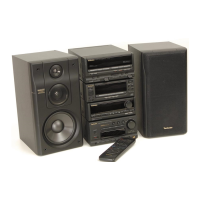
Technics SC-CH570 Service Manual

Technics SC-CH570
37 pages
To Next Page IconTo Next Page
To Previous Page IconTo Previous Page
Page #4 background imageLoading...
Page #4 background image
RS-CH770
Remove
the
flat
cable
from
connector.
cD
Release
the
4
claws,
and
then
remove
the
front
panel
ass’y.
Connector
(CN901-—1/CNS01—2)
Main
P.C.B.
Connect
the
flat
cable
to
the
connector.
Connector
(CN6O1A)
Release
the
2
claws,
and
then
remove
the
power
supply
P.C.B..
Socket
(CN601B)
Power
supply
P.C.B.
t
step
9
Connect
the
socket
(CN601B)
to
the
connector
(CN601A).
*
Check
the
main
P.C.B.
and
power
supply
P.C.B.
as
shown
below.
Main
P.C.B.
istep
10)
Connect
the
lead
wire.
Cabinet
Place
the
power
supply
P.C.B.
on
the
insulation
material
not
to
short-circuit
the
solder
side
of
power
supply
P.C.B..
(i)
+
(Black)
[XTBS3HJFZ1]

Other manuals for Technics SC-CH570

Questions and Answers:

Question and Answer IconNeed help?

Do you have a question about the Technics SC-CH570 and is the answer not in the manual?

Technics SC-CH570 Specifications

General IconGeneral
BrandTechnics
ModelSC-CH570
CategoryStereo System
LanguageEnglish

Related product manuals