mi
CONTENTS
Page
SAFETY
PRECAUTION
..........-:sccscesssnssssnesescsssennensensnrersesenssnensesnenses
WIRING
CONNECTION
DIAGRAM.............::.:ssessscsstsessststrsnensnennes
22
PROTECTION
CIRCUITRY.........-:ssssssecssssescens
PRINTED
CIRCUIT
BOARDG.......2...sccseesssstesnssessnsessenoresseraces
23~27
a4
BEFORE
REPAIR
AND
ADJUSTMENT
TERMINAL
GUIDE
OF
IC’S,
TRANSISTORS
AND
DIODES.....
28
ey
LINE-UP
COMPONENTS
......ccsscesesssssstsans
TERMINAL
FUNCTION
OF
IC..........ccsceccseceecsssotsnnsstsocsonsansnteaneaes
i
FRONT
PANEL
CONTROLG.........
REPLACEMENT
PARTS
LIST......
{=
DISASSEMBLY
INSTRUCTIONS
ate
CABINET
PARTS
LOCATION
.....
A
FAN
MOTOR
TROUBLE
SHOOTING
GUIDE..........--------s-ssseseeseen
9
REPLACEMENT
PARTS
LIST
...........00+s000
f
BLOCK
DIAGRAM..........s:scs:sssscsessesesersensnsenseetsnunennenneatassessess
10~12
RESISTORS
AND
CAPACITORS
PACKAGING
.......sssccsrserscnssssesnsnsnsanesuesseserseensenseasnenensensnanesenenensees
4,
SCHEMATIC
DIAGRAM
-sssscssssssssssstesnsssaneseneestensnsesnees
13~21
Note:
Refer
to
the
placement,
Equipment
connections
and
Remote
control
operation
of
Service
manual
for
Model
No.
ST-K55
(PP),
Order
No.
AD9401001C1.
=
:
Mi
SAFETY
PRECAUTION
(this
“safety
precaution”
is
applied
only
in
U.S.A.)
.
Before
servicing,
unplug
the
power
cord
to
prevent
an
electric
shock.
.
When
replacing
parts,
use
only
manufacturer’s
recommended
components
for
safety.
.
Check
the
condition
of
the
power
cord.
Replace
if
wear
or
damage
is
evident.
.
After
servicing,
be
sure
to
restore
the
lead
dress,
insulation
barriers,
insulation
papers,
shields,
etc.
.
Before
returning
the
serviced
equipment
to
the
customer,
be
sure
to
make
the
following
insulation
resistance
test
to
prevent
the
customer
from
being
exposed
to
a
shock
hazard.
¢
INSULATION
RESISTANCE
TEST
1.
Unplug
the
power
cord
and
short
the
two
prongs
of
the
plug
with
a
jumper
wire.
2.
Turn
on
the
power
switch.
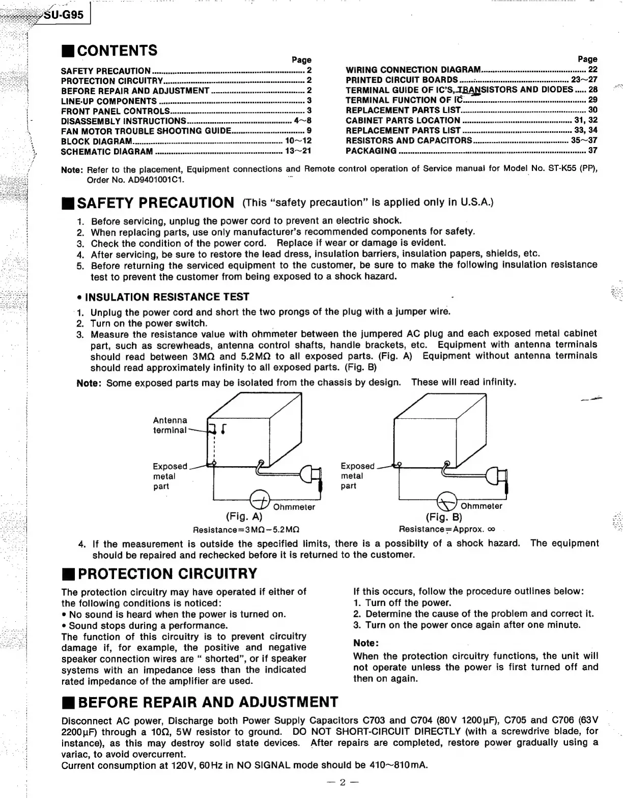
3.
Measure
the
resistance
value
with
ohmmeter
between
the
jumpered
AC
plug
and
each
exposed
metal
cabinet
part,
such
as
screwheads,
antenna
control
shafts,
handle
brackets,
etc.
Equipment
with
antenna
terminals
should
read
between
3MQ
and
5.2MQ
to
all
exposed
parts.
(Fig.
A)
Equipment
without
antenna
terminals
should
read
approximately
infinity
to
all
exposed
parts.
(Fig.
B)
Note:
Some
exposed
parts
may
be
isolated
from
the
chassis
by
design.
These
will
read
infinity.
aAhROD
Antenna
terminal
Exposed
Exposed
metal
metal
‘
part
part
:
Ohmmeter
(Fig.
A)
(Fig.
B)
Resistance=3MQ—-5.2MQ
Resistance=Approx.
oo
4.
If
the
measurement
is
outside
the
specified
limits,
there
is
a
possibilty
of
a
shock
hazard.
The
equipment
should
be
repaired
and
rechecked
before
it
is
returned
to
the
customer.
Mi
PROTECTION
CIRCUITRY
Ohmmeter
The
protection
circuitry
may
have
operated
if
either
of
the
following
conditions
is
noticed:
¢
No
sound
is
heard
when
the
power
is
turned
on.
¢
Sound
stops
during
a
performance.
The
function
of
this
circuitry
is
to
prevent
circuitry
damage
if,
for
example,
the
positive
and
negative
speaker
connection
wires
are
“
shorted”,
or
if
speaker
systems
with
an
impedance
less
than
the
indicated
rated
impedance
of
the
amplifier
are
used.
Mi
BEFORE
REPAIR
AND
ADJUSTMENT
If
this
occurs,
follow
the
procedure
outlines
below:
1.
Turn
off
the
power.
2.
Determine
the
cause
of
the
problem
and
correct
it.
3.
Turn
on
the
power
once
again
after
one
minute.
Note:
When
the
protection
circuitry
functions,
the
unit
will
not
operate
unless
the
power
is
first
turned
off
and
then
on
again.
Disconnect
AC
power,
Discharge
both
Power
Supply
Capacitors
C703
and
C704
(80V
1200uUF),
C705
and
C706
(63V
2200u1F)
through
a
100,
5W
resistor
to
ground.
DO
NOT
SHORT-CIRCUIT
DIRECTLY
(with
a
screwdrive
blade,
for
instance),
as
this
may
destroy
solid
state
devices.
After
repairs
are
completed,
restore
power
gradually
using
a
variac,
to
avoid
overcurrent.
Current
consumption
at
120V,
60Hz
in
NO
SIGNAL
mode
should
be
410~810mA.
—2—
 Loading...