2
Planning principles
Blow direction of the fan always from the outside to the inside!
If the fan blows from the inside to the outside, there is a danger of warm and thus humid air
following from adjacent building parts thus increasing the problem!
A supply air fan is usually sufficient!
The “exhaust air” is pushed out through leaks in the building. With building that are very leak-
proof, an overflow opening (flap, …) must be created. If supply and exhaust fans are used, the
efficiency of the exhaust fan must never be above that of the supply fan.
The ventilated buildings (the ventilated room) must be as leak-proof as possible!
In order to prevent unwanted penetration of humid air through natural circulation, windows and
doors should be closed.
In order to (especially in the winter) keep the cooling of rooms within limits, timer-controlled
interval operation is useful. An additional minimum temperature monitoring can be imple-
mented.
The exterior humidity sensor must not be directly subjected to insolation or rain. If neces-
sary, the sensor will be protected with a small shield.
Operation
The large display contains the symbols for all important information and a plain text area. Naviga-
tion with the coordinate keys is matched to the display sequence.
Navigation keys for selecting the display and for changing parameters.
Entry to a menu, release of a value for changing with the navigation keys (enter key).
Return from the menu level selected last, exit from the parameterising of a value (return
key).
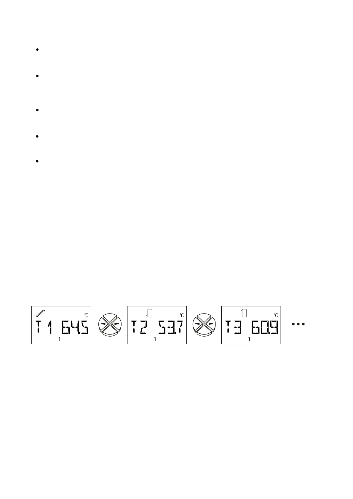
The side keys are the navigation keys for selecting the required display such as e.g. collector
or tank temperature during regular operation. A different sensor symbol and the corresponding tem-
perature are displayed for each pressure.
The appropriate symbol is displayed for information above the text line (according to the example
of the collector temperature). The choice of symbol has no effect on the control function. All instruc-
tion during parameterisation are below the text line.
To the side of the display, the currently active outputs are identifiable on the
green illuminated figures 1–3.
 Loading...