3 of 12 © 2009 W 422 - 03/09
Electrical Drawings
Module Installation
The electrical drawing examples on the following
pages show the 422 in common applications Choose the
drawing that most accurately depicts the components in
your system and use that drawing as a guide to aid in
wiring your system.
These are only concept drawings, not engineered drawings.
They are not intended to describe a complete system nor
any particular system. It is up to the system designer to
determine the necessary components for and configuration
of the particular system being designed including additional
equipment isolation relays (for loads greater than the
controls specified output ratings) and any safety devices
which in the judgement of the designer are appropriate in
order to properly size, configure and design that system
and to ensure compliance with building and safety code
requirements.
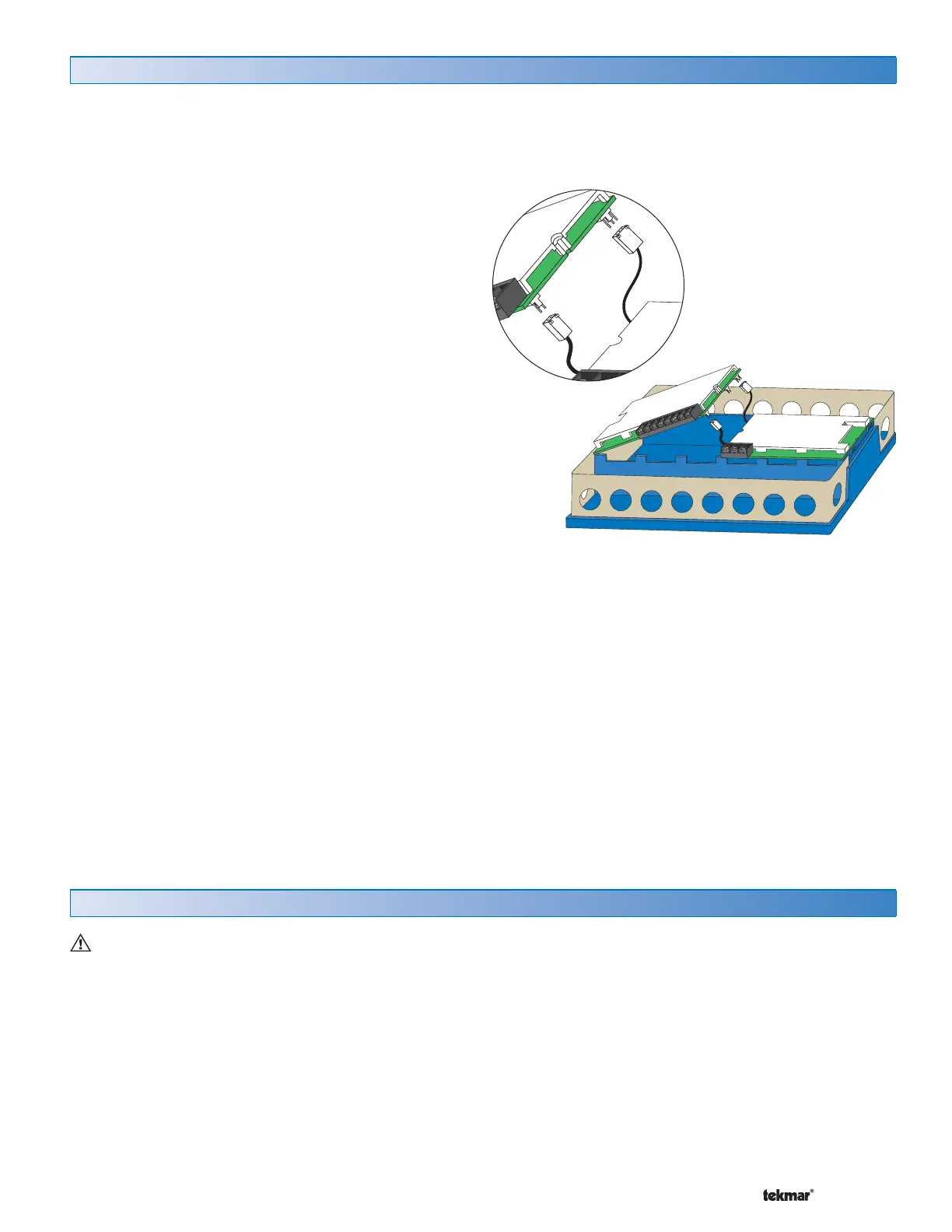
Install the Universal Reset Module 422 in the left side of a tekmarNet
®
4 (tN4) wiring enclosure. The enclosure comes with
a Zone Manager pre-installed in the right side. Review the figure below to understand the installation of the 422:
To Install the 422
1. Remove the front cover of the wiring enclosure by
removing the two screws.
2. Remove the left side blank by removing the centre screw
holding the blank and the Zone Manager in place. Make
sure the Zone Manager stays in place.
3. Discard the blank.
4. The 422 has connector pins protruding from the underside
of the board. The Zone Manager has wiring harnesses
with plugs that connect to these pins.
Remove the required wiring harnesses from their
retaining clips in the enclosure.
5. Carefully connect the Zone Manager’s plugs onto the
pins on the underside of the 422.
• There is one smaller gauge connector with three pins and
one larger gauge connector with 2 pins. These connectors
can be installed only one way. Take care to ensure a good
connection and avoid bending the pins.
6. Lower the 422 into the enclosure at an angle. Insert the
two tabs on the left side of the 422 in to the correspond-
ing slots in the left side of the wiring enclosure.
7. Lower the 422 toward the center of the enclosure until
the two halves fit together. Make sure that the connector
wires are placed underneath without pinching the wire.
8. Replace the center screw to hold the two controls in
place.
9. Strip all wiring to a length of 3/8 in. or 10 mm for all
terminals.
 Loading...