Circuit Description—475
the external trigger input connector, or a sample of the line
voltage connected to the instrument. Controls are provided
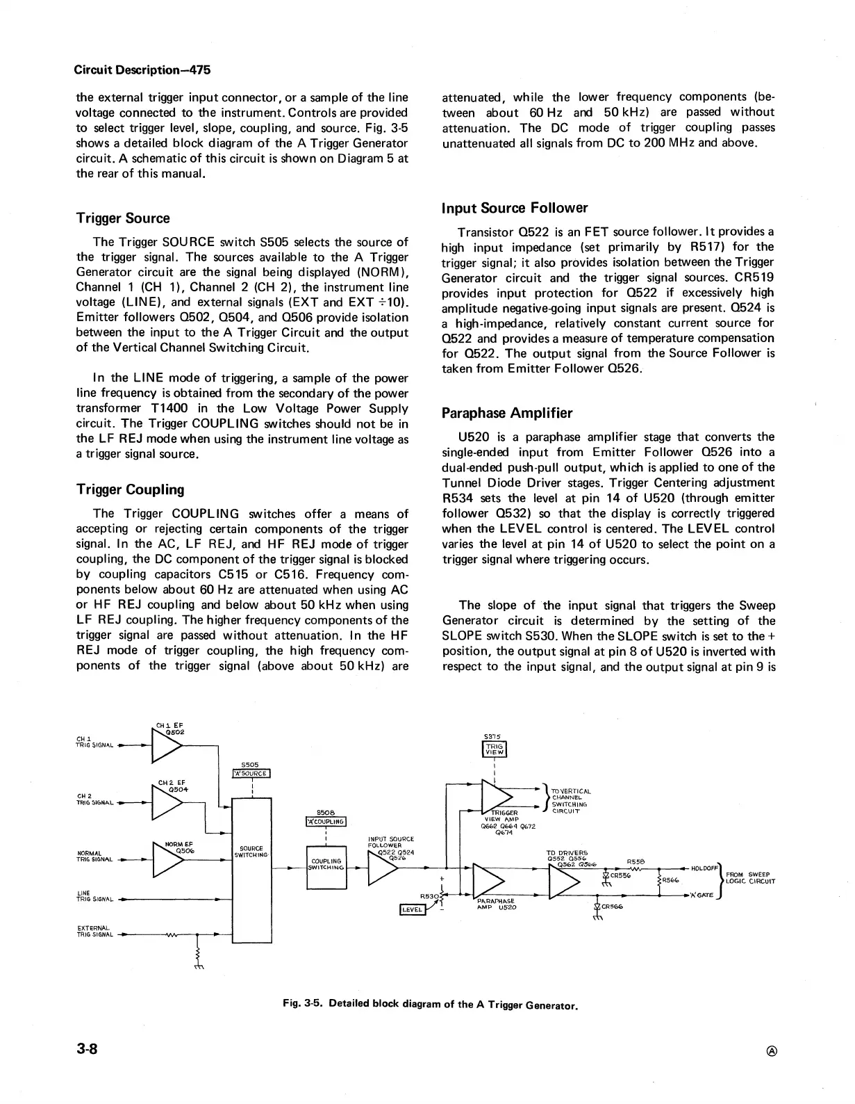
to select trigger level, slope, coupling, and source. Fig. 3-5
shows a detailed block diagram of the A Trigger Generator
circuit. A schematic of this circuit is shown on Diagram 5 at
the rear of this manual.
Trigger Source
The Trigger SOURCE switch S505 selects the source of
the trigger signal. The sources available to the A Trigger
Generator circuit are the signal being displayed (NORM),
Channel 1 (CH 1), Channel 2 (CH 2), the instrument line
voltage (LINE), and external signals (EXT and EXT -MO).
Emitter followers Q502, Q504, and Q506 provide isolation
between the input to the A Trigger Circuit and the output
of the Vertical Channel Switching Circuit.
In the LINE mode of triggering, a sample of the power
line frequency is obtained from the secondary of the power
transformer T1400 in the Low Voltage Power Supply
circuit. The Trigger COUPLING switches should not be in
the LF REJ mode when using the instrument line voltage as
a trigger signal source.
Trigger Coupling
The Trigger COUPLING switches offer a means of
accepting or rejecting certain components of the trigger
signal. In the AC, LF REJ, and HF REJ mode of trigger
coupling, the DC component of the trigger signal is blocked
by coupling capacitors C515 or C516. Frequency com
ponents below about 60 Hz are attenuated when using AC
or HF REJ coupling and below about 50 kHz when using
LF REJ coupling. The higher frequency components of the
trigger signal are passed without attenuation. In the HF
REJ mode of trigger coupling, the high frequency com
ponents of the trigger signal (above about 50 kHz) are
attenuated, while the lower frequency components (be
tween about 60 Hz and 50 kHz) are passed without
attenuation. The DC mode of trigger coupling passes
unattenuated all signals from DC to 200 MHz and above.
Input Source Follower
Transistor Q522 is an FET source follower. It provides a
high input impedance (set primarily by R517) for the
trigger signal; it also provides isolation between the Trigger
Generator circuit and the trigger signal sources. CR519
provides input protection for Q522 if excessively high
amplitude negative-going input signals are present. Q524 is
a high-impedance, relatively constant current source for
Q522 and provides a measure of temperature compensation
for Q522. The output signal from the Source Follower is
taken from Emitter Follower Q526.
Paraphase Amplifier
U520 is a paraphase amplifier stage that converts the
single-ended input from Emitter Follower Q526 into a
dual-ended push-pull output, which is applied to one of the
Tunnel Diode Driver stages. Trigger Centering adjustment
R534 sets the level at pin 14 of U520 (through emitter
follower Q532) so that the display is correctly triggered
when the LEVEL control is centered. The LEVEL control
varies the level at pin 14 of U520 to select the point on a
trigger signal where triggering occurs.
The slope of the input signal that triggers the Sweep
Generator circuit is determined by the setting of the
SLOPE switch S530. When the SLOPE switch is set to the +
position, the output signal at pin 8 of U520 is inverted with
respect to the input signal, and the output signal at pin 9 is
FROM SWEEP
LOGIC CIRCUIT
3-8
®
Fig. 3-5. Detailed block diagram of the A Trigger Generator.

 Loading...


