Circuit Description—475
applied to Q1318 and prevents the amplitude of oscillations
from increasing. This prevents the CRT cathode supply
from going more negative than approximately —3300 volts.
High-Voltage Rectifiers and Output
The high-voltage transformer T1320 has two output
windings. One winding provides filament voltage for the
cathode-ray tube. The filament voltage can be supplied
from the High-Voltage Supply, since the cathode-ray tube
has a very low filament current drain. The filament of the
cathode-ray tube is elevated to the cathode level to prevent
cathode-to-filament arcing. The other winding of T1320 is
used to derive both the negative cathode potential and the
positive anode accelerating potential. The CRT grid bias
voltage is derived by a DC restorer circuit that uses a sample
of the signal in the high-voltage winding in conjunction
with DC levels provided by the Z-Axis Amplifier and the
negative CRT cathode potential.
The positive accelerating potential is supplied by High
Voltage Multiplier U1321. Regulated output voltage is
approximately +15,500 volts. The negative cathode poten
tial is supplied by a voltage doubler circuit. Voltage output
is —2450 volts. Variations in supply voltage are monitored
by the High-Voltage Regulator circuit to provide a regu
lated high-voltage output.
In the 0.1 s, 0.2 s, 0.5 s, and X-Y positions of the
TIM E/D IV switch the anode of CR1337 is connected to
ground. This limits how negative the operating level at the
emitter of Q1338 can go to reduce the unblanking
capabilities of the amplifier, thereby reducing the possi
bility of inadvertently burning the CRT phosphor. When
the BEAM FIND pushbutton is pushed —8 volts is
connected to the junction of R 1342 and R1346. This biases
Q1338 off which in turn causes CR1343 to be reverse
biased. Now the output of the Z-Axis Amplifier is isolated
from all of the circuit's normal signal inputs. The output
level of the amplifier is set at a fixed level determined by
the parallel value of R1343 and R1346 divided into the
feedback resistance of the amplifier.
CRT Control Circuits
Focus of the CRT display is controlled by FOCUS
control R1380. ASTIG adjustment R1397, which is used in
conjunction with the FOCUS control to provide a well-
defined display, varies the positive level on the astigmatism
grid. Geometry adjustment R1390 varies the positive level
on the horizontal deflection plate shields to control the
overall geometry of the display.
Two adjustments control the trace alignment by varying
the magnetic field around the CRT. Y Align adjustment
R1385 controls the current through L1385, which affects
the CRT beam after vertical deflection but before hori
zontal deflection. Therefore, it affects only the vertical (Y)
components of the display. TRACE ROTATION adjust
ment R1386 controls the current through L I386 and
affects both vertical and horizontal rotation of the beam.
Z-Axis Amplifier
The Z-Axis Amplifier circuit controls the CRT intensity
level from several inputs. The effect of these input signals is
to either increase or decrease the trace intensity, or to
completely blank portions of the display. The input
transistor Q1338 is a current-driven, low input impedance
amplifier. It provides termination for the input signals as
well as isolation between the input signals and the following
stages. The current signals from the various control sources
are connected to the emitter of Q1338 and the algebraic
sum of the signals determines the collector conduction
level.
Q1344, Q1352, Q1354, Q1358, and Q1362 compose a
feedback amplifier stage. R1369 is the feedback element.
C l352 provides high-frequency compensation. Q1344 is an
emitter follower that provides drive to the output comple
mentary amplifier made up of Q1352, Q1354, and Q1358.
Q1358 is a device with higher frequency characteristics
than Q1354 and is used to improve the overall frequency
capabilities of the Z-Axis Amplifier. On the fast positive
going output signal peaks, Q1358 depletes the charge on
C1358. Then, on the negative-going signal peaks, Q1362 is
pulsed on to renew the charge on C1358. CR1367 provides
protection to the Z-Axis Amplifier circuitry in the event of
short duration arcing in the CRT High-Voltage Power
Supplies.
®
3-19
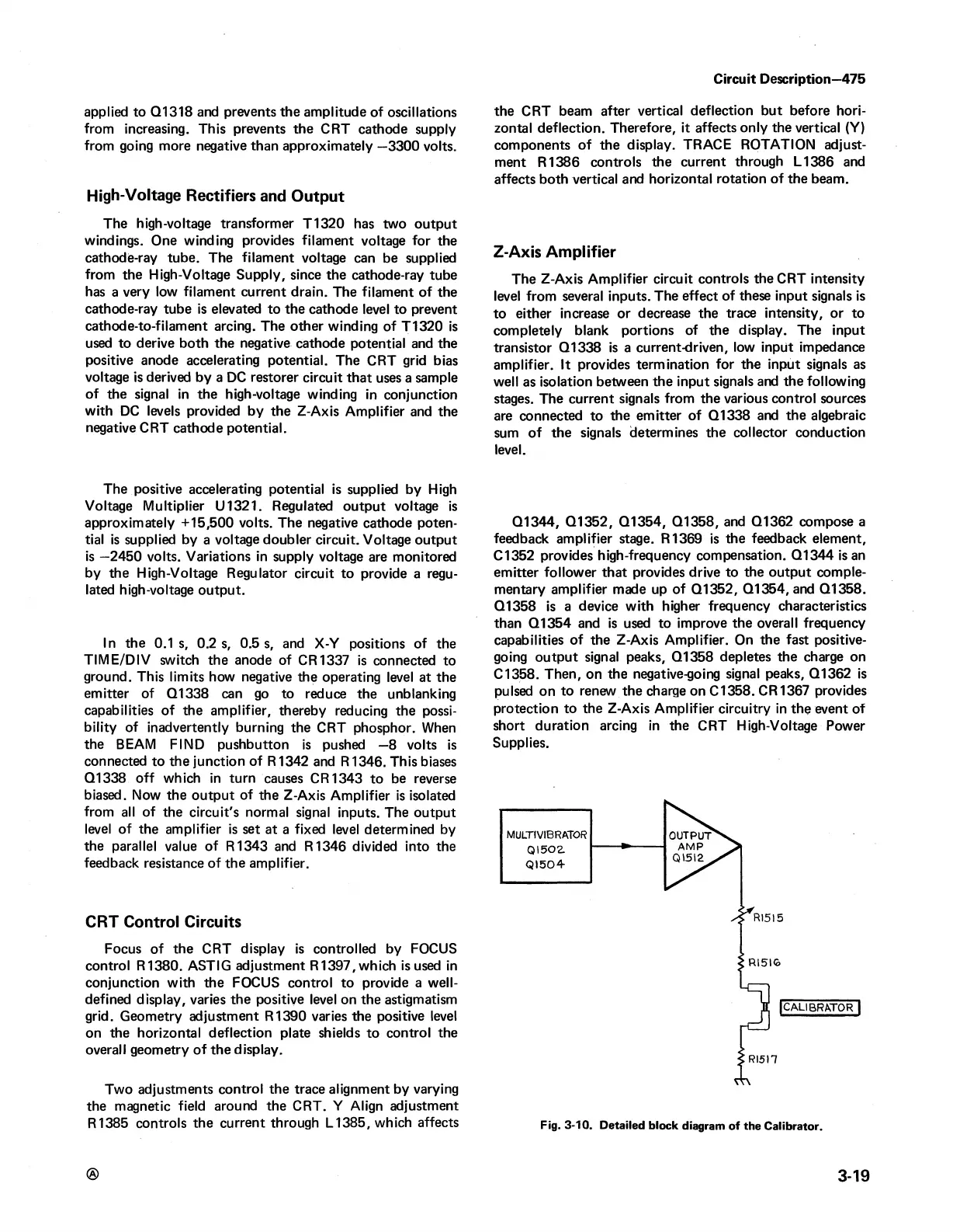
Fig. 3-10. Detailed block diagram of the Calibrator.

 Loading...


