Calibration—475
TABLE 5-1 (cont)
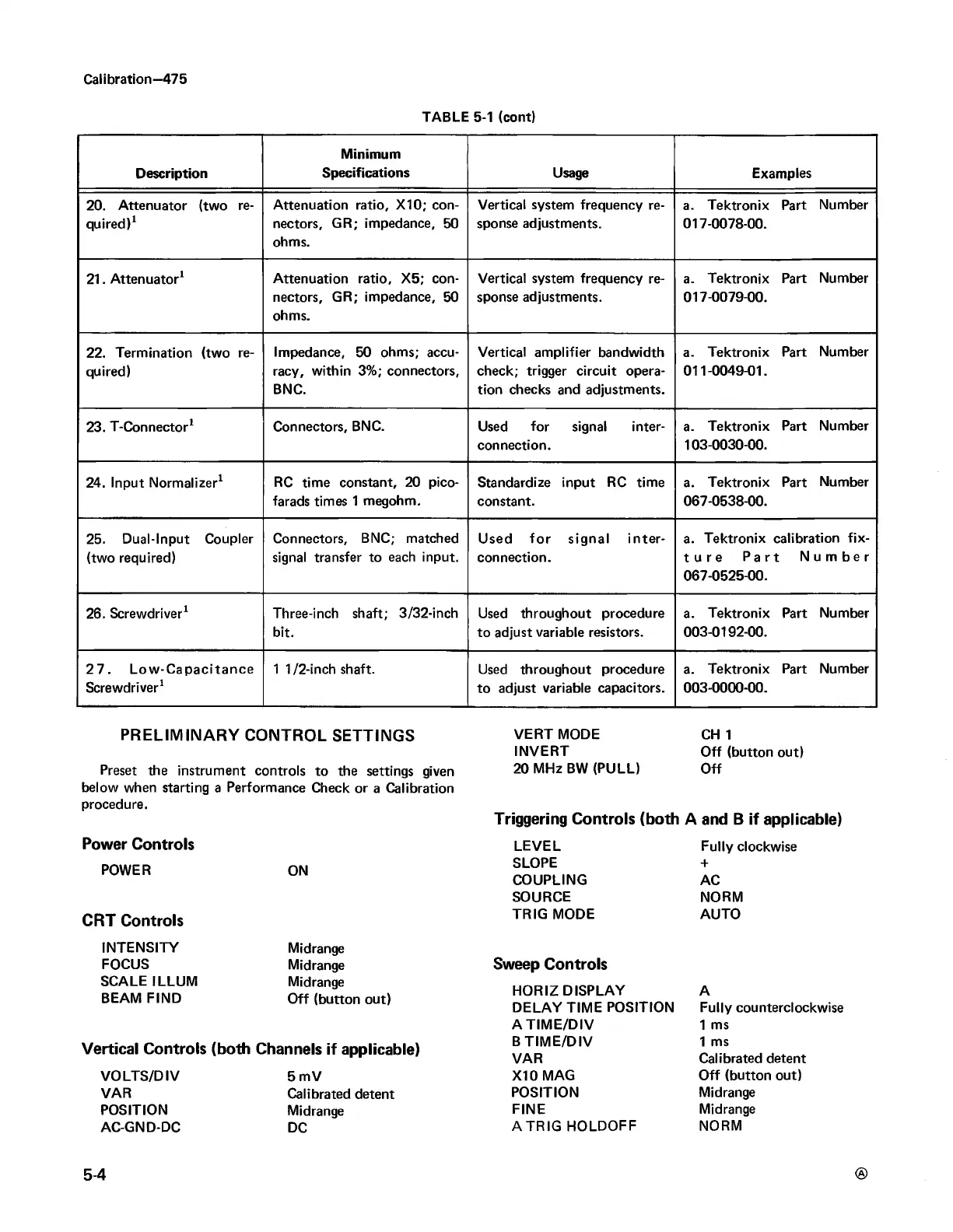
Description
Minimum
Specifications Usage
Examples
20. Attenuator (two re
quired)1
Attenuation ratio, X10; con
nectors, GR; impedance, 50
ohms.
Vertical system frequency re
sponse adjustments.
a. Tektronix Part Number
017-0078-00.
21. Attenuator1
Attenuation ratio, X5; con
nectors, GR; impedance, 50
ohms.
Vertical system frequency re
sponse adjustments.
a. Tektronix Part Number
017-0079-00.
22. Termination (two re
quired)
Impedance, 50 ohms; accu
racy, within 3%; connectors,
BNC.
Vertical amplifier bandwidth
check; trigger circuit opera
tion checks and adjustments.
a. Tektronix Part Number
011-0049-01.
23. T-Connector1 Connectors, BNC. Used for signal inter
connection.
a. Tektronix Part Number
103-0030-00.
24. Input Normalizer1
RC time constant, 20 pico
farads times 1 megohm.
Standardize input RC time
constant.
a. Tektronix Part Number
067-0538-00.
25. Dual-Input Coupler
(two required)
Connectors, BNC; matched
signal transfer to each input.
Used fo r signal inter
connection.
a. Tektronix calibration fix-
ture Part Number
067-0525-00.
26. Screwdriver1
Three-inch shaft; 3/32-inch
bit.
Used throughout procedure
to adjust variable resistors.
a. Tektronix Part Number
003-0192-00.
2 7 . Low -Capacitance
Screwdriver1
1 1/2-inch shaft.
Used throughout procedure
to adjust variable capacitors.
a. Tektronix Part Number
003-0000-00.
PRELIMINARY CONTROL SETTINGS
Preset the instrument controls to the settings given
below when starting a Performance Check or a Calibration
procedure.
Power Controls
POWER ON
CRT Controls
INTENSITY
FOCUS
SCALE ILLUM
BEAM FIND
Midrange
Midrange
Midrange
Off (button out)
Vertical Controls (both Channels if applicable)
VO LTS/DIV
VAR
POSITION
AC-GND-DC
5 mV
Calibrated detent
Midrange
DC
VERT MODE
INVERT
20 MHz BW (PULL)
CH 1
Off (button out)
Off
Triggering Controls (both A and B if applicable)
LEVEL
SLOPE
COUPLING
SOURCE
TRIG MODE
Fully clockwise
+
AC
NORM
AUTO
Sweep Controls
HORIZ DISPLAY
DELAY TIME POSITION
A T IM E /D IV
B T IM E /D IV
VAR
X I0 MAG
POSITION
FINE
A TR IG HOLDOFF
A
Fully counterclockwise
1 ms
1 ms
Calibrated detent
Off (button out)
Midrange
Midrange
NORM
5-4

 Loading...


