c. Adjust the A LEVEL control for a stable display.
Calibration—475
e. CHECK-Using the CH 2 VOLTS/DIV switch and the
Standard Amplitude Calibrator settings given in Table 5-2,
check that the vertical deflection factor is within the given
tolerance in each position of the CH 2 VOLTS/DIV switch. d. CHECK—Duration of each cycle is about 1 division.
9. Check Channel 1 and 2 Variable Volts/Division
Range
a. Set both VOLTS/DIV switches to 20 mV.
b. Adjust the Standard Amplitude Calibrator for a 0.1
volt output.
c. Rotate the CH 2 VAR control fully counter
clockwise.
d. CHECK—CRT display reduces to less than 2
divisions.
e. Set the CH 1 AC-GND-DC switch to DC and the
VERT MODE switch to CH 1.
f. Rotate the CH 1 VAR control fully counterclockwise.
g. CHECK—CRT display reduces to less than 2 divisions.
h. Return both VAR controls to the detent positions.
i. Disconnect the test setup.
10. Check Alternate Mode Operation
a. Set the VERT MODE switch to ALT and the A
LEVEL control fully clockwise.
b. Position the traces 2 divisions apart.
c. CHECK—That the sweeps alternate in all settings of
the T IM E /D IV switch except X-Y.
11. Check Chop Mode Operation
a. Set the A TIM E /D IV switch to 1 jus, the A SOURCE
switch to NORM, and the VERT MODE switch to CHOP.
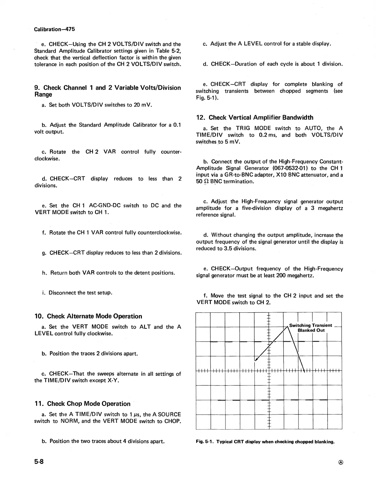
e. CHECK—CRT display for complete blanking of
switching transients between chopped segments (see
Fig. 5-1).
12. Check Vertical Amplifier Bandwidth
a. Set the TRIG MODE switch to AUTO, the A
TIM E /D IV switch to 0.2 ms, and both VOLTS/DIV
switches to 5 mV.
b. Connect the output of the High-Frequency Constant-
Amplitude Signal Generator (067-0532-01) to the CH 1
input via a GR-to-BNC adapter, X I0 BNC attenuator, and a
50 £2 BNC termination.
c. Adjust the High-Frequency signal generator output
amplitude for a five-division display of a 3 megahertz
reference signal.
d. Without changing the output amplitude, increase the
output frequency of the signal generator until the display is
reduced to 3.5 divisions.
e. CHECK—Output frequency of the High-Frequency
signal generator must be at least 200 megahertz.
f. Move the test signal to the CH 2 input and set the
VERT MODE switch to CH 2.
b. Position the two traces about 4 divisions apart.
Fig. 5-1. Typical CRT display when checking chopped blanking.

 Loading...


