Calibration—475
f. CHECK—For LOW LINE indicator light to turn on
when the autotransformer is below 103 volts.
g. Return the autotransformer for a 115 VAC output.
2. Check High Voltage Power Supply
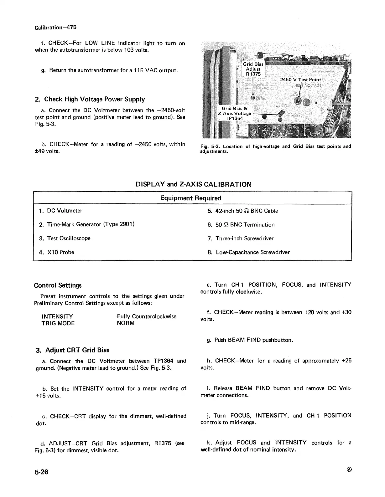
a. Connect the DC Voltmeter between the -2450-volt
test point and ground (positive meter lead to ground). See
Fig. 5-3.
b. CHECK—Meter for a reading of —2450 volts, within
±49 volts.
Fig. 5-3. Location of high-voltage and Grid Bias test points and
adjustments.
DISPLAY and Z-AXIS CALIBRATION
Equipment Required
1. DC Voltmeter
5. 42-inch 50 £2 BNC Cable
2. Time-Mark Generator (Type 2901)
6. 50 £2 BNC Termination
3. Test Oscilloscope
7. Three-inch Screwdriver
4. X I0 Probe
8. Low-Capacitance Screwdriver
Control Settings
Preset instrument controls to the settings given under
Preliminary Control Settings except as follows:
INTENSITY Fully Counterclockwise
TRIG MODE NORM
3. Adjust CRT Grid Bias
a. Connect the DC Voltmeter between TP1364 and
ground. (Negative meter lead to ground.) See Fig. 5-3.
b. Set the INTENSITY control for a meter reading of
+15 volts.
c. CHECK—CRT display for the dimmest, well-defined
dot.
d. ADJUST—CRT Grid Bias adjustment, R1375 (see
Fig. 5-3) for dimmest, visible dot.
e. Turn CH 1 POSITION, FOCUS, and INTENSITY
controls fully clockwise.
f. CHECK—Meter reading is between +20 volts and +30
volts.
g. Push BEAM FIND pushbutton.
h. CHECK—Meter for a reading of approximately +25
volts.
i. Release BEAM FIND button and remove DC Volt
meter connections.
j. Turn FOCUS, INTENSITY, and CH 1 POSITION
controls to mid-range.
k. Adjust FOCUS and INTENSITY controls for a
well-defined dot of nominal intensity.
5-26

 Loading...


