Tektronix AFG3000 Series Function Generator Guide v1.0 Portland State University
15
Example:
You connect a function generator with output impedance R
O
= 50 Ω to a test circuit which has a load
resistance of R
L
. You configure the generator to output a sinusoid of amplitude V
SET
= 1 V
p-p
at frequency
f
SET
. The voltage V
L
across the load is monitored with an oscilloscope using a 1× probe. The oscilloscope
has an input resistance of R
in
= 1M Ω in parallel with an input capacitance of C
in
= 15 pF.
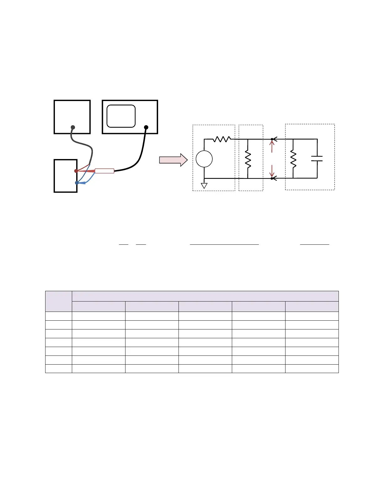
Figure 11: Example test circuit with oscilloscope
The function generator “sees” the load in parallel with the oscilloscope’s input impedance:
SET
OEQ
EQ
L
LinininL
Lin
in
inL
CinLEQ
V
RZ
Z
V
RRCjRR
RR
Cj
RR
ZRRZ
in
+
=→
++
=
++==
−
2
11
||||
1
ω
ω
Table 3: Calculated load voltage V
L
versus load resistance R
L
at specific signal frequencies f
SET
Given V
SET
= 1 V
p-p
, R
in
= 1M
Ω
, C
in
= 15 pF
R
L
(Ω)
L
SET
SET
SET
SET
SET
Function
Generator
V
G
V
L
R
O
R
L
Function
Generator
Test
Circuit
Test
Circuit
R
in
Probe
C
in
Ground
 Loading...


