Description
CT-1/CT-2 Current Transformer
3
100%
90%
80%
70%
60%
Frequency (Hz)
100 k 1 M10 k1 k
0.5 A
DC
0 A
DC
1 A
DC
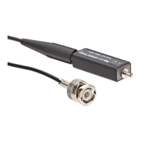
This response was obtained with the + side of the CT-2 facing the
signal source (preferred connection)
10 M 100 M
Figure 3: CT-2 frequency response vs. DC current
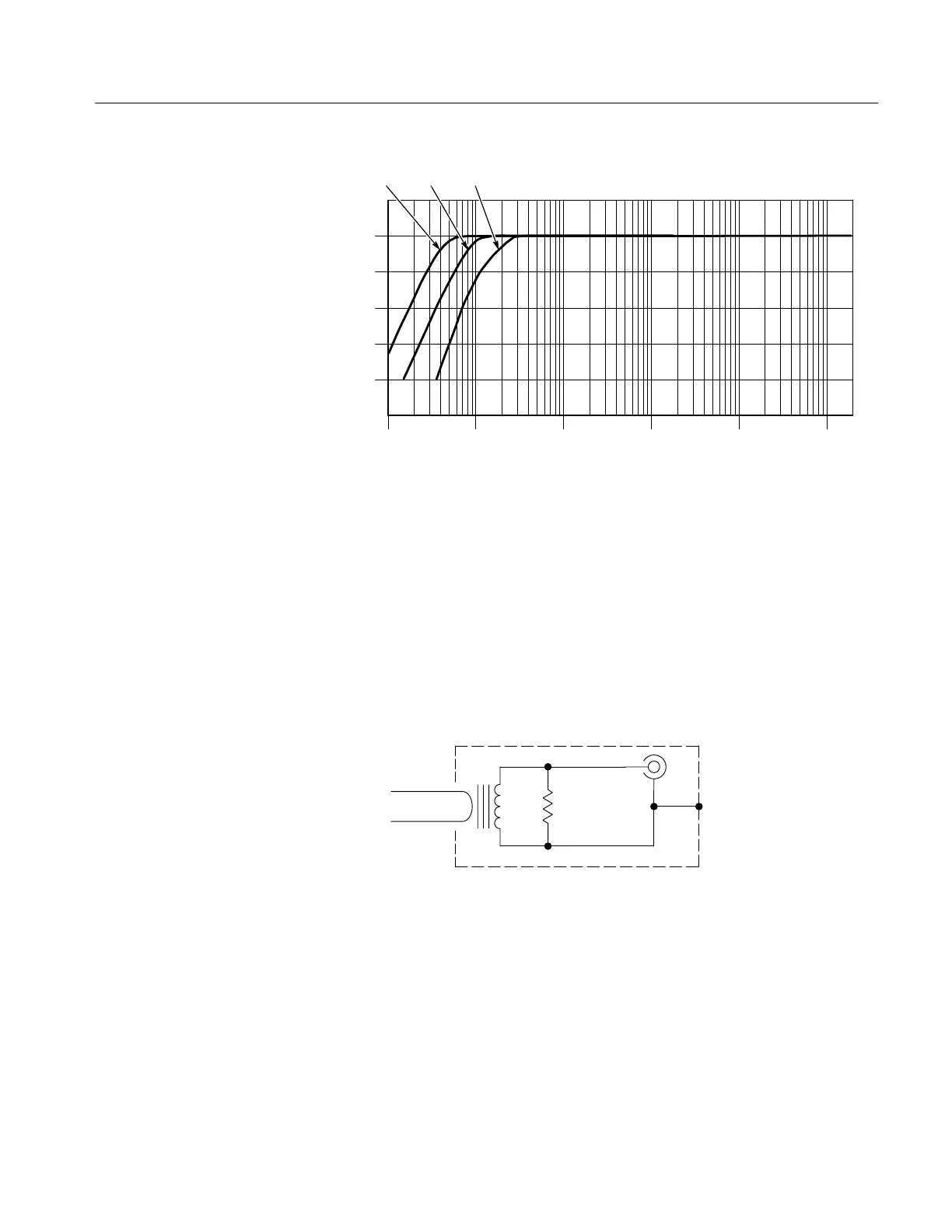
The CT-1 and CT-2 consist of a current transformer and a flexible probe
cable that attaches between the transformer and the oscilloscope. In
addition, the CT-1 and CT-2 have an internal termination resistor that
reduces reflections that allows the transformer to be disconnected from the
probe cable and left in the circuit. Figure 4 shows a simplified circuit of the
CT-1 and CT-2.
Input circuit
50 W
Figure 4: CT-1 and CT-2 simplified circuit
 Loading...