Installation Instructions
Acquisition Board Replacement
9
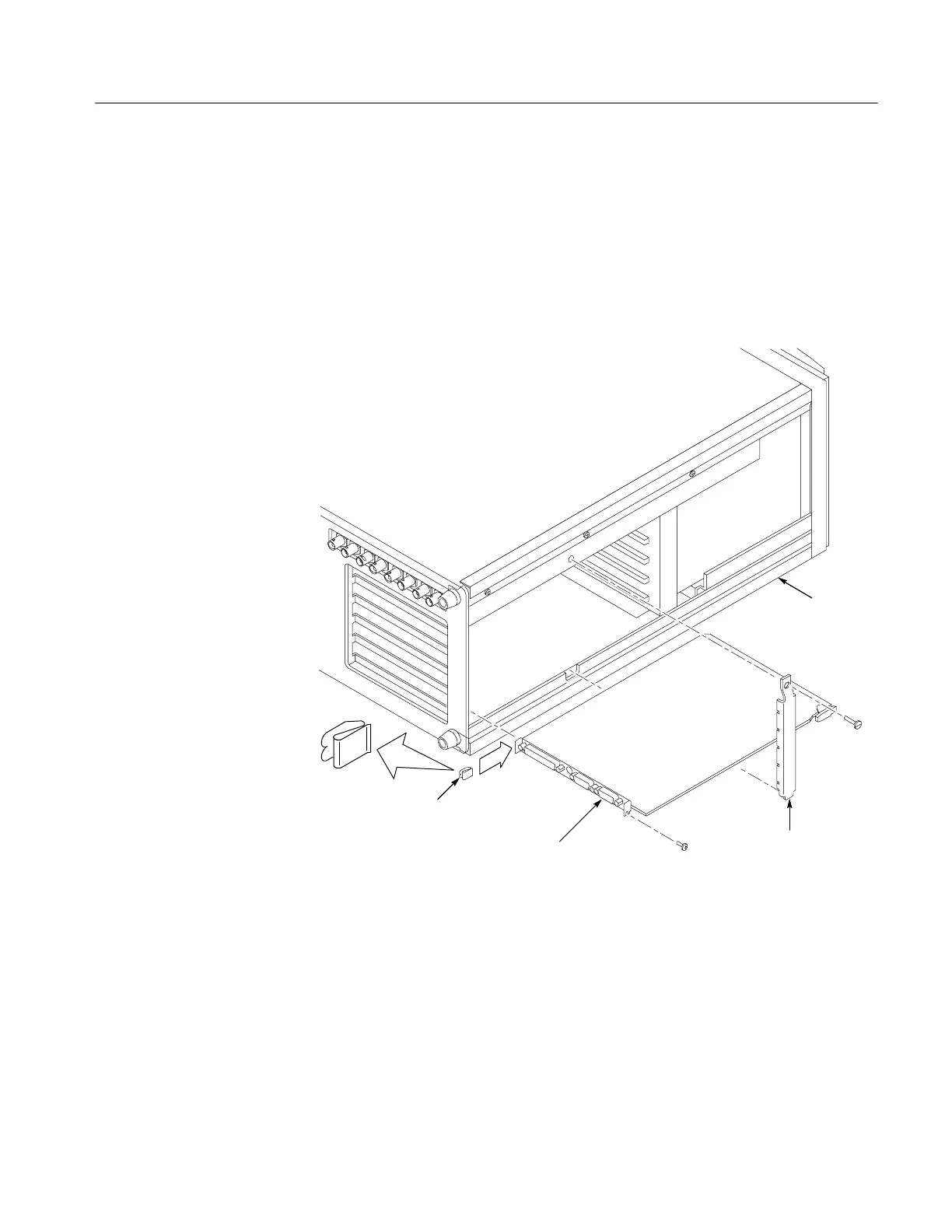
1. Remove the screw holding the C PU I/O (A20) circuit board. The CPU I/O
circuit board (A20) is located in the bottom slot of the card cage.
2. Pull the CPU I/O (A20) circuit board out, just exposing the rear panel
connectors from the card cage.
3. Attach the EMI clip to the rear of the CPU I/O circuit board (A20) as shown
in Figure 4.
CPU I/O (A20 board)
EMI clip
Left side
Circuit board
retainer bar
Figure 4: Location of the EMI clip on the CPU I/O board
4. Push the CPU I/O circuit board (A20) into the card cage. Attach and tighten
the one screw.
5. Replace the vertical bar and screw.
6. Reinstall the left-side cover panel.
EMI Clip for
CPU I/O Board

 Loading...


