Bill of Materials (BOM)
3-3
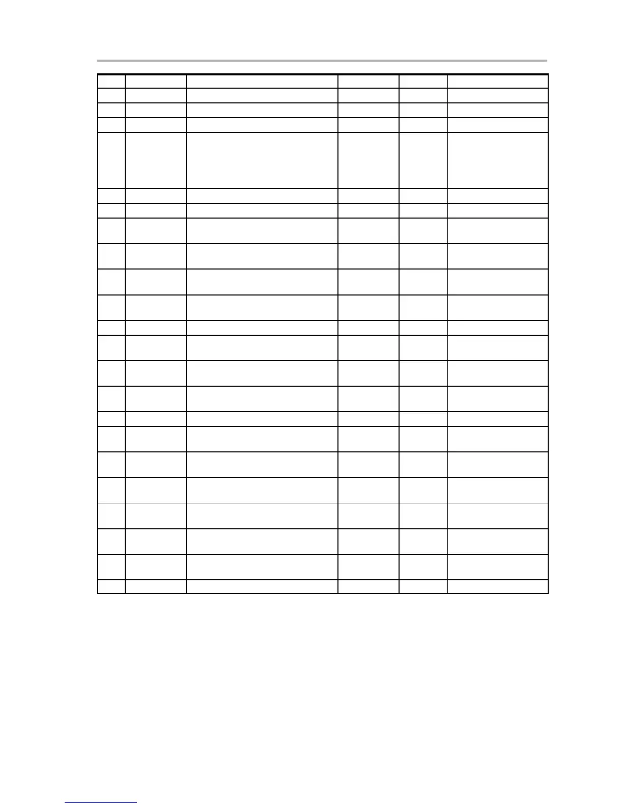
EV2300 Bill of Materials, Component Placement, Schematic
Qty Part NumberMFRSizeDescriptionRef Des
1 R53 Resistor, chip, 0 Ω, 1/16 W, 5% 603 Std Std
1 R54 Resistor, chip, 113 kΩ, 1/16 W, 0.1% 603 Vishay TNPW06031133BT9RT1
1 R6 Resistor, chip, 1.5 kΩ, 1/16 W, 5% 603 Std Std
0 R7, R10−R12,
R17, R20,
R25, R28,
R36−R38,
R40
Open 603
2 R8, R9 Resistor, chip, 33 Ω, 1/16 W, 5% 603 Std Std
0 SW1 Open 5 mm × 5 mm
2 U1, U2 IC, Single bus buffer gate with 3−state
output, with negative enable
DCK TI SN74LVC1G125DCK
1 U3 IC, Single bus buffer gate with 3−state
output, with positive enable
DCK TI SN74LVC1G126DCK
1 U4 IC, USB, general purpose, device
controller
0.480 × 0.480” TI TUSB3210PM
1 U5 IC, ultra low-power LDO regulator,
3.3 V, 50 mA
SOT23-5 TI TPS77033DBV
1 U6 IC, Advance gas gauge DBT38 TI bq8015DBT
1 Y1 or Y4 Cryatal, high performance, 12.00 MHz,
SMT
0.126 × 0.126 Citizen or
Daishinku
CSA-309−12.000MABJ
or DSX630G-12.00MHz
0 Y2 or Y3 Crystal, 32,768 MHz, 7−12 pF
capacitance
1.9mm × 5mm Daishinku
or ECS
DST520G-32.768kHz or
ECS-.327-8-14
1 N/A Plastic enclosure, bone, Texas
Instruments silkscreen
PacTec 84107−501−039
Wire Cable Assembly
1 Mate Connector, female, 0.100 centers 22−01−30
47
Molex
4 N/A Terminals, crimp, tin 08−50−011
4
Molex
N/A Wire, insulated 22 Awg, red, 18 inches
(± 3 inches) (VOUT)
Any Any
N/A Wire, insulated 22 Awg, white, 18
inches (± 3 inches) (SCL)
Any Any
N/A Wire, insulated 22 Awg, black, 18
inches (± 3 inches) (GND)
Any Any
N/A Wire, insulated 22 Awg, brown, 18
inches (± 3 inches) (SDA)
Any Any
1 N/A Heatshrink 1” Any Any
Notes: 1) These assemblies are ESD sensitive, ESD precautions should be observed.
2) These assemblies must be clean and free from flux and all contaminants. Use of no clean flux is not acceptable.
3) These assemblies must comply with workmanship standards IPC-A-610 Class 2.
4) Reference designators marked with an asterik (*) cannot be substituted. All other components can be substituted
with equivalent manufacturers components.
5) Make one EEPROM connector wire assembly for each assembly produced, from J15 mate, 4 − 22 AWG wires and
crimp terminals. Wire colors for pin numbers are listed below. Strip and tin flying leads 0.25 inches from end of wire.
Red − pin #4 (signal VOUT)
Brown − pin #3 (signal SDA)
White − pin #2 (signal SCL)
Black − pin #1 (GND)

 Loading...