9 ALTERING COVERAGE AT 2m
MOUNTING HEIGHT
INS 317-2
12 GRADE 3 ANTI-MASKING
14 LED FUNCTIONS
• The Prestige AMDT Plus is designed to meet both EN 50131-1 and
TS 50131-2-4 and as such is a future-proof solution.
• On either power-up or reapplication of the front cover the detector will
temporarily enter an auto-optimisation mode to adapt to it’s environment. This
will be shown by the LED’s flashing in sequence.
• During optimisation ensure that there are no obstructions in close proximity (<1m)
to the detector that will not be present during normal operation, as this could
trigger a false masking signal.
• During installation avoid mounting the detector where objects may interfere with
the anti-masking function (<1m), above doors, near curtains etc.
• The detector should not be mounted in direct sunlight.
• Masking is signalled by the fault and alarm relay opening simultaneously.
A fault will be indicated by one of the following:
• Supply input voltage out of specification
• PIR sensor malfunction
• Microwave sensor malfunction
The fault will be cleared once the condition has been resolved.
Self-Test
To meet the requirements of TS 50131-2-4 this detector is capable of performing a
self-test. There are two types of self-test; a local self-test and a remote self-test.
Local Self-Test
Local self-test is controlled by the detector and runs periodically to test the functionality
of the circuitry. Setting SW4 to off can disable this function. If the test is passed no
indication is shown but if it fails then a fault will be signalled to the panel and the orange
LED lit (if enabled). The fault will remain until a local or remote test is passed.
Remote Self-Test
This test is initiated at the control panel. If the test is passed then the detector will signal
an alarm. If the test fails then the detector will signal a fault. The fault will remain until a
local or remote test is passed. There is a dedicated control type for this output on Texecom
Premier panels, expanders and keypads for ease of installation. For more information on
setting up an output to run this test please see the relevant manual.
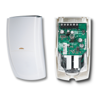
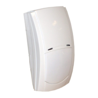
18 PHYSICAL
60mm
(2.4”)
40mm
(1.6”)
112.25mm
(4.4”)
2.5mm (0.1”) ABS
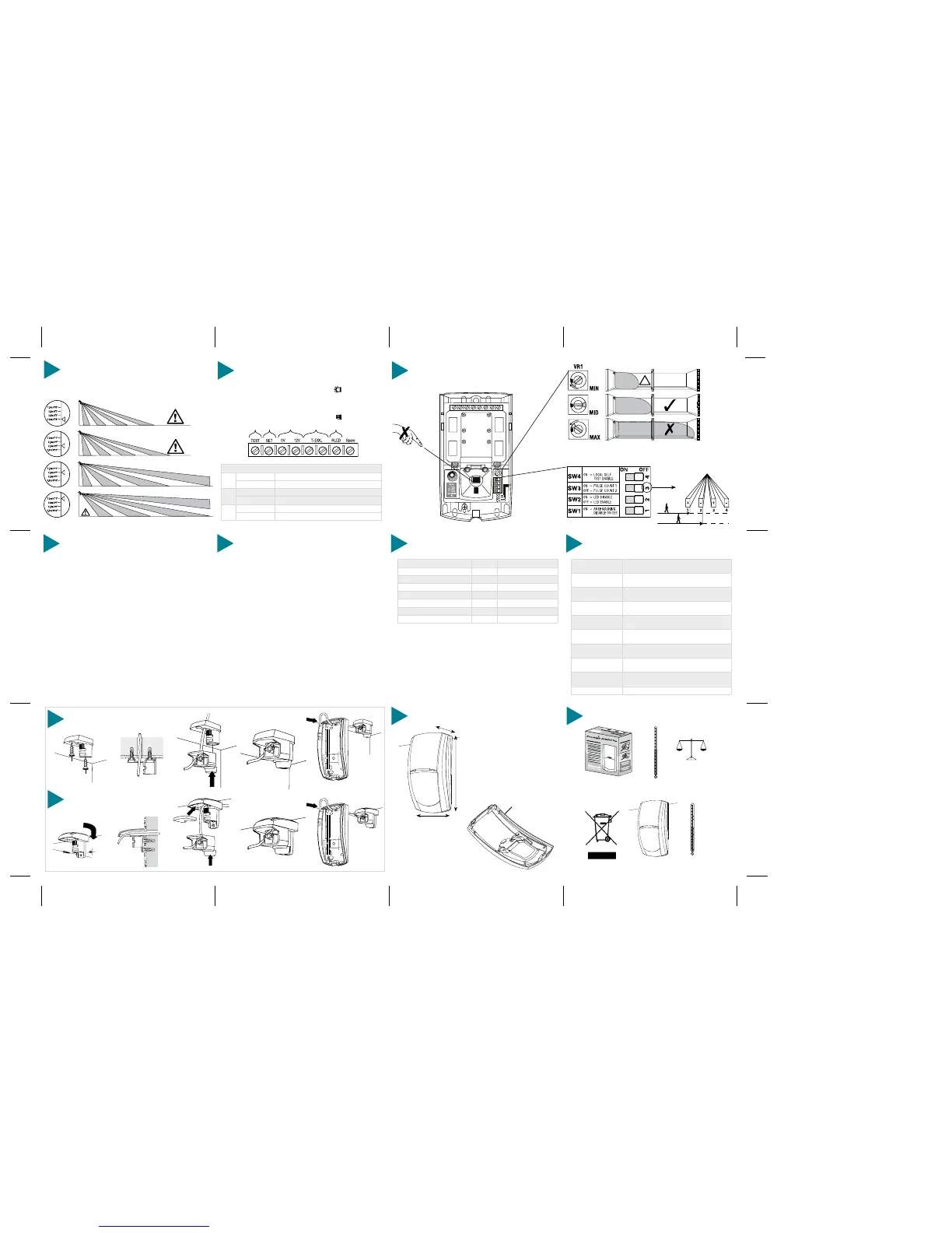
19 ENVIRONMENTAL
-35°C (-31°F) to +60°C (+140°F)
150g (5oz) approx.
-35°C (-31°F) to +55°C (+131°F)
15 STANDARDS & APPROVALS
Detector Standard:
TS 50131-2-4 Grade 3 Environmental Class II.
System Standard:
Suitable for use in a PD 6662/BS EN 50131-1 Grade
3 system, Environmental Class II.
EMC:
Independently certified to BS EN 50130-4 : 1996.
RF Immunity:
No false alarms from 80MHz to 2GHz at 10V/m.
Complies with BS EN 61000-4-3 : 2002.
Electrostatic
Discharge:
No false alarms up to 8kV.
Complies with BS EN 61000-4-2 : 1995.
Fast Transient
Immunity:
No false alarms up to ±4kV.
Complies with BS EN 61000-4-4 : 1995.
High Energy
Transient Immunity:
No false alarms up to ±2kV.
Complies with BS EN 61000-4-5 : 1995.
Conducted RF
Susceptibility:
No false alarms at 10Vrms.
Complies with BS EN 61000-4-5 : 1995.
Conducted &
Radiated Emissions:
Complies with EN 55022 Class B.
Product Identifier:
AMDT Plus
1 3 FAULT MONITORING
Detector Status LED Indication
Alarm: Both LED's Red
PIR Detection: Right LED Green
Microwave Detection: Left LED Orange
Masking: Left LED Flashing Green
Fault: Right LED Flashing Orange
Masking & Microwave Detection: Left LED Alternating Green and Orange
Fault And PIR Detection: Right LED Alternating Green and Orange
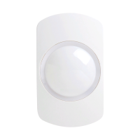
10 WIRING & DETECTOR SET-UP
INPUT FUNCTIONS:
RLED:
12V/No connection: LED’s will function in accordance with the setting of SW2
0V: LED’s will not function even if they are enabled via SW2
SET:
12V/No connection: Detector is in the Standby/unset mode
0V: Detector is in the Alert/set mode
TEST:
12V/No connection: Normal operation
0V: Initiate remote self-test
*Not for use in a Grade 3 system
 Loading...