Do you have a question about the Tokyo Hy-Power HL-45B and is the answer not in the manual?
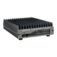
Solid-state HF/50MHz band linear power amplifier with 45W max output power.
Designed for YAESU FT-817 with auto band selection and send-receive switching via control cable.
Uses a pair of RF MOS FET power transistors (RD30HVF1) for high reliability and stability.
Features over-voltage and over-drive protection circuits, including shutdown for 11 meter band.
LED power level meter indicates relative output power level for operator convenience.
Covers HF Band (1.8-28MHz) and 50MHz Amateur Bands for versatile operation.
Supports SSB (A3E), CW (A1A), and FM (F3E) transmission modes.
Provides 45W maximum output power for SSB (PEP) and CW.
Requires a maximum RF drive power of 5W for optimal performance.
Operates on DC 13.8V, consuming a maximum of 8.5A.
Features 50 Ohm impedance for both input and output connections.
Uses SO-239 connectors for RF input and output.
Includes Class AB amp, LPFs, protection, LED meter, remote switching, and ALC.
Utilizes two RD30HVF power transistors from Mitsubishi Electric.
Compact dimensions: 150(W) x 47(H) x 211(D) mm (5.9 x 1.9 x 8.3 inches).
Weighs approximately 1.6 kgs (3.4 lbs).
Optional cable available for non FT-817 radios for remote control.
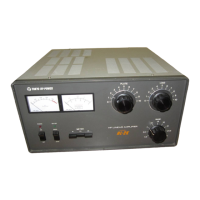
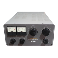
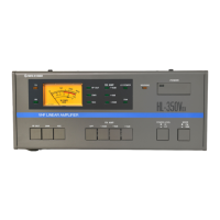
Details front panel power switch, band select, protection LED, and power level indicators.
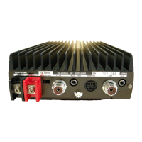
Details rear panel connectors for RF input/output, remote control, and DC power.
Illustrates typical connection setup for the HL-45B with an FT-817 transceiver.
Illustrates connection setup for the HL-45B with transceivers other than FT-817.
Guide to connecting equipment, checking SWR, and powering on the amplifier.
Details on transmitting, power level indication, and SWR checks during operation.
Instructions on how to turn off the amplifier and bypass its functions.
Note on connecting remote control cables for non-FT-817 radios.
Emphasizes the maximum input RF drive power limit of 5W.
Details the pin assignments for the 8-pin DIN REMOTE socket.
Specifies required connections (TX GND, GND, ALC) for other radios.
Explains ALC's role in preventing distortion and limiting output power.
Identifies the ALC adjustment potentiometer on the bottom plate.
Guide to adjusting the ALC pot for optimal output or to prevent decline.
Details protection modes (bypass) triggered by excessive drive power or voltage.
Instructions to reset protection by cycling the power switch twice.
Advice on maintaining heat sink temperature and ensuring proper ventilation.
Recommendations for low SWR antennas and solid coaxial connections.
Warnings against exceeding RF input limits and using incorrect DC voltages.
Guidance on selecting a stable power supply with adequate current capacity.
Addresses RF stray issues and suggests using ferrite cores for mitigation.
Instructions for installing capacitors and clip-on ferrite cores.
Diagram showing the RF signal flow through the amplifier's components.
Highlights the protection circuit and control logic based on ICs.
Solid-state HF/50MHz band linear power amplifier with 45W max output power.
Designed for YAESU FT-817 with auto band selection and send-receive switching via control cable.
Uses a pair of RF MOS FET power transistors (RD30HVF1) for high reliability and stability.
Features over-voltage and over-drive protection circuits, including shutdown for 11 meter band.
LED power level meter indicates relative output power level for operator convenience.
Covers HF Band (1.8-28MHz) and 50MHz Amateur Bands for versatile operation.
Supports SSB (A3E), CW (A1A), and FM (F3E) transmission modes.
Provides 45W maximum output power for SSB (PEP) and CW.
Requires a maximum RF drive power of 5W for optimal performance.
Operates on DC 13.8V, consuming a maximum of 8.5A.
Features 50 Ohm impedance for both input and output connections.
Uses SO-239 connectors for RF input and output.
Includes Class AB amp, LPFs, protection, LED meter, remote switching, and ALC.
Utilizes two RD30HVF power transistors from Mitsubishi Electric.
Compact dimensions: 150(W) x 47(H) x 211(D) mm (5.9 x 1.9 x 8.3 inches).
Weighs approximately 1.6 kgs (3.4 lbs).
Optional cable available for non FT-817 radios for remote control.
Details front panel power switch, band select, protection LED, and power level indicators.
Details rear panel connectors for RF input/output, remote control, and DC power.
Illustrates typical connection setup for the HL-45B with an FT-817 transceiver.
Illustrates connection setup for the HL-45B with transceivers other than FT-817.
Guide to connecting equipment, checking SWR, and powering on the amplifier.
Details on transmitting, power level indication, and SWR checks during operation.
Instructions on how to turn off the amplifier and bypass its functions.
Note on connecting remote control cables for non-FT-817 radios.
Emphasizes the maximum input RF drive power limit of 5W.
Details the pin assignments for the 8-pin DIN REMOTE socket.
Specifies required connections (TX GND, GND, ALC) for other radios.
Explains ALC's role in preventing distortion and limiting output power.
Identifies the ALC adjustment potentiometer on the bottom plate.
Guide to adjusting the ALC pot for optimal output or to prevent decline.
Details protection modes (bypass) triggered by excessive drive power or voltage.
Instructions to reset protection by cycling the power switch twice.
Advice on maintaining heat sink temperature and ensuring proper ventilation.
Recommendations for low SWR antennas and solid coaxial connections.
Warnings against exceeding RF input limits and using incorrect DC voltages.
Guidance on selecting a stable power supply with adequate current capacity.
Addresses RF stray issues and suggests using ferrite cores for mitigation.
Instructions for installing capacitors and clip-on ferrite cores.
Diagram showing the RF signal flow through the amplifier's components.
Highlights the protection circuit and control logic based on ICs.
| Brand | Tokyo Hy-Power |
|---|---|
| Model | HL-45B |
| Category | Amplifier |
| Language | English |