260 Series Tractor Service Manual 5 - 9
GEAR DRIVE
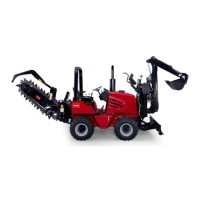
9. Remove the cotter pin and washer from the shift
lever rod and remove the shift lever rod (Figure
196).
Figure 196
MVC-273X
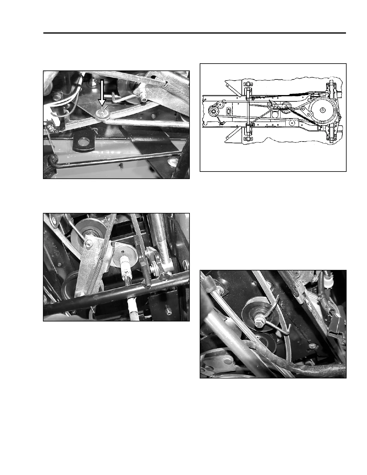
10. Remove the idler pulley assembly at the pivot bolt
(Figure 197).
Figure 197
MVC-275X
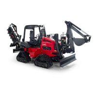
Belt Routing Diagram
Figure 198
Bell Route 2
11. Install the new belt through the idler pulley
assembly, around the V-idler pulley and the flat
idler pulley. Reinstall the pivot bolt for the idler
assembly.
12. Take the slack of the belt forward over the
steering sector, over each tie rod and around the
engine drive pulley. Starting from the front, make
sure the belt fits between the belt guide and idler
pulley, on the right side of the engine drive pulley
(Figure 199).
Figure 199
MVC-276X
 Loading...