Specifications
• Body Style:
• AVB, 3/4" Female NPT (EZF-29-03)
• AVB, 1" Female NPT (EZF-29-04)
• Flow range (3/4"): 0.25–20 GPM
• Flow range (1"): 0.25–30 GPM
• Operating pressure: 10–150 PSI
• Solenoid:
24 V a.c., 60Hz (nominal)
19 V a.c., 60Hz (minimum)
Inrush: 0.40 amps, 11.50 VA @ 24 V a.c.
Holding: 0.20 amps, 5.75 VA @ 24 V a.c.
• Friction Loss:
GPM Flow
0.25 5 10 15 20 30
PSI Loss (3/4") 2.0 4.2 4.2 4.8 7.6 –
(1") 2.0 2.1 3.1 2.3 3.8 8.1
Installation Procedure
1. From the shut-off valve, route a supply pipe to the valve
installation site. For UV protection, use dark gray
Schedule 80 PVC on the inlet (pressurized) side of the
valve and all PVC pipe installed above ground. Use
Class 200 PVC on the underground sprinkler lines.
2. Flush the supply line thoroughly to remove all traces of
dirt and debris.
3. Prepare two 1" slip/male thread adapters with three to five
complete wraps of teflon tape, evenly covering the threads.
CAUTION:
Use only Teflon
TM
tape on threaded valve
connections. Pipe dope will damage plastic threads.
4.
Install the threaded adapters into the valve and tighten
securely. Using PVC primer and cement, install the valve to
the PVC pipe as shown in
Figure 1.
5. Route a multi-wire, direct-burial sprinkler valve cable
from the sprinkler timer to the valve location. If the cable
run is less than 800', 18-gauge wire is sufficient. For dis-
tances from 800'–2000', 14-gauge wire is recommended.
6. Using wire splice connectors, attach either wire from
each valve solenoid to the white cable wire. This wire is
designated as the valve common wire. Connect the
remaining wire from the solenoid to one of the color-
coded cable wires. Ensure all wire connections are
secure and waterproof.
CAUTION: Use grease caps or waterproof connec-
tors on all wire splice connections to prevent corrosion,
connection failure and short circuit.
7. At the sprinkler timer, connect the white common wire to
the output terminal labeled “C” or “COM.” Connect each
color-coded valve wire to the numbered output
terminals in the order you wish the valves to operate dur-
ing the automatic watering cycle.
8. Open the shut-off valve from the water source. Test valve
operation using the timer or manually at the valve.
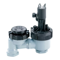
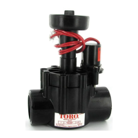
EZ-Flo
TM
Plus Automatic Anti-Siphon Valve Models EZF-29-03 & EZF-29-04
Installation and Operating Instructions
6" (minimum)
SCH 80 PVC Pipe
From Water Source
Slip x Male Thread
PVC Adapters
Manual Shut-Off Valve
Use SCH 80 PVC
Above Ground
Class 200 PVC
Underground
Figure 1
Valve Installation Guidelines
Ensure the following requirements, in addition to all local code require-
ments, are met when installing the EZ-Flo Plus Anti-Siphon Valve:
• The installed height, measured from the valve base, must not be less
than of 6" above the highest downstream outlet controlled by the valve.
• The anti-siphon valve must not be subject to standing water which can
rise to less than 6" from the base of the valve.
• The anti-siphon valve must not be installed indoors (some spillage may
occur) or in a valve box below ground level.
• The installation site must be accessible to allow inspection and servicing.
• Additional control valves must
not be installed downstream of the anti-
siphon valve.
• The anti-siphon valve must be installed vertically with the top of the anti-
siphon cap level.
• The valve must not be operated continuously for more than 12 hours in
any 24-hour period.
• Installing a manual shut-off valve between the main water supply and
automatic valve or valve manifold is recommended for ease of valve
maintenance and sprinkler system winterization.
Figure 2
Grease Cap
Wire Connector
Valve Common Wire
Multi-Wire
Cable From Timer