42
Adjusting the Belt Tension
Each cutting unit drive belt is individually tensioned by a
self tensioning spring loaded idler. When the idlers are
properly adjusted, the black plastic sleeve should be 0.12 to
0.25 in. (3 to 6 mm) from the edge of the idler support.
When 0.50 in. (13 mm) of the plastic sleeve is exposed, an
adjustment is required. To assure proper operation of the
cutting unit, check adjustment of spring loaded idler after
first 10 hours of operation and every time maintenance on
the belt is required.
1. Lower cutting unit to the shop floor. Remove belt
covers from center and wing cutting units.
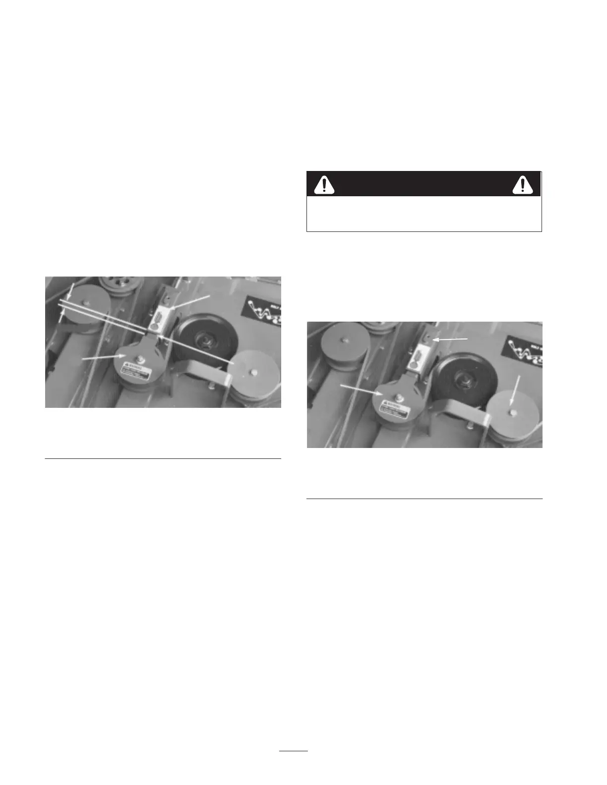
2. Measure the length of the exposed black plastic sleeve
(Fig. 71). If distance is 0.12–0.25 in. (3–6 mm), spring
loaded idler is properly adjusted and belt tension is
correct. If dimension is not correct, proceed to next
step.
0.12–0.25 in.
(3–6 mm)
1
2
3
Figure 71
1. Spring loaded idler
2. Idler support
3. Black, plastic sleeve
3. Loosen the 2 flange head nuts securing idler adjustor
tube to top of cutting deck.
4. Loosen jam nut on adjusting screw and rotate screw
until the black plastic sleeve is flush (even) with the
edge of idler support.
5. When distance is attained, tighten jam nut on adjusting
screw and the 2 flange head nuts securing idler adjustor
tube to top of cutting deck.
6. Check adjustment on other adjustors and repeat
procedure if required.
Replacing the Drive Belts
The blade drive belts are very durable, but after many hours
of use, the belts will show signs of wear. Signs of a worn
belt are: squealing when belt is rotating, blades slipping
when cutting grass, frayed edges, burn marks and cracks.
Replace a belt if any of these conditions are evident.
Removing the Wing Deck Belts
Idler pulley spring loaded, use caution when
relieving spring tension on wing belt.
Warning
1. Lower cutting unit to the shop floor. Remove belt
covers from center and wing cutting units.
2. To relieve tension on wing belt, pull back on idler
pulley until holes in idler adjustor tube and tube sleeve
are aligned (Fig. 72). Thread a 5/16 in. capscrew into
holes retaining parts.
1
2
3
Figure 72
1. Spring loaded idler pulley
2. Stationary idler pulley
3. Aligned holes
3. Remove hair pin cotter securing clutch rod to front of
cutting deck and disconnect rod from deck. Unplug
clutch wire from harness (Fig. 73).
4. To ease wing belt removal, loosen or remove stationary
idler pulley next to wing’s inner spindle pulley.

 Loading...