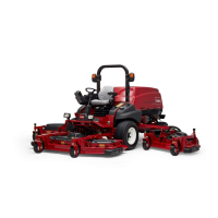
Remove the castor fork shaft and spacer assembly
from the castor arm (Fig. 10). Place spacers onto
the castor spindle to the desired height-of-cut
setting and install the castor fork shaft in arm (Fig.
9). Install the remaining spacers onto the shaft and
secure the assemblies with the lynch pin (Fig. 10).
Figure 10
1. Lynch pin
2. Spacers
3. Washers
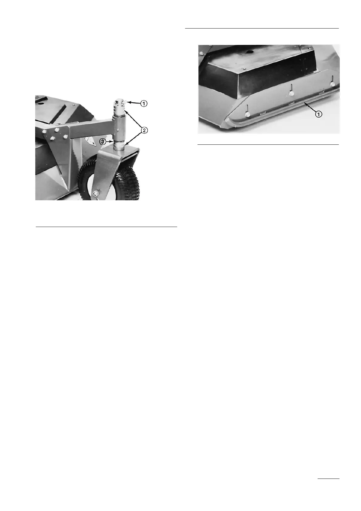
ADJUSTING SKIDS
After the initial set up or if height of cut is changed, deck
skids should also be adjusted. Adjust skids by loosening the
flange lock nuts (Fig. 11), positioning the skid at the
specified height (see chart) and re-tightening the flange lock
nuts.
Front Cutting Unit
All height of cut—0.95cm to 1.2 cm above level surface
Outboard Cutting Units
2.5 cm height of cut—Skid positioned all the way up
3.8 cm to 7.6 cm height of cut—Skid positioned 1.2 cm to
2.5 cm above level surface.
7.6 cm and above height of cut—Skid positioned all the
way down,
Figure 11
1. Skid
Before Operating
15

 Loading...