Specifications
• Radius: 55’–92’ (16,8–28m)
• Flow rate: 14.1–61.3 GPM (53,4-232
LPM)
• Arc: Bidirectional, part circle rotation,
adjustable from 40-330, and true
unidirectional 360 full-Circle rotation.
• Pilot Valve-selectable at 50, 65, 80 or 100
psi (3,5, 4,5, 5,5 and 6,9 Bar)
• Recommended operating pressure range:
65–100 psi (4,5–6,9 Bar)
• Maximum pressure: 150 psi (10,3 Bar)
• Minimum pressure: 40 psi (2,8 Bar)
• Activation types – Electric Valve-in-Head:
- Standard Solenoid:
▪ 24 VAC, 50/60 Hz
▪ Inrush: 0.30 A
▪ Holding 0.20 A
- Spike Guard Solenoid:
▪ 24 VAC, 50/60 Hz
▪ Inrush: 0.12 A
▪ Holding 0.10 A
- Nickel-Plated Spike Guard Solenoid:
▪ 24 VAC, 50/60 Hz
▪ Inrush: 0.12 A
▪ Holding 0.10 A
- DC Latching Solenoid (DCLS):
▪ Momentary low voltage pulse
- Integrated GDC Module w/DCLS:
▪ Momentary low voltage pulse
• Stator variations: 3
• Inlet size: 1.5” (40mm) ACME
• Body height: 11 5/8” (295mm)
• Compartment cover diameter: 7
5
/
8
”
(194mm)
• Pop-up height to nozzle: 3¼” (83mm)
• Pop-up height (overall): 4
3
/
16
” (106mm)
• Weight:
▪ 5.08 lbs. (2,3 kg)
▪ 5.80 lbs. (2,6 kg) Integrated GDC
Module
• Three inline nozzles; rotating stream
pattern
• Precipitation rates:
▪ Minimum: 0.45”/hr. (11,4mm/hr.)
▪ Maximum: 0.94/hr. (23,9mm/hr.)
• Main nozzles: 9 (51, 52, 53, 54, 55, 56, 57,
58 and 59)
• Selectable nozzle trajectory: 15 or 25
• Apex and Radius:
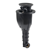
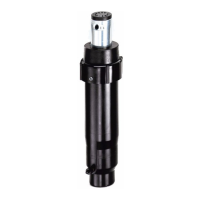
Bidding Specifications
The sprinkler body assembly shall consist of
five significant components:
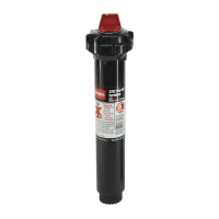
• The sprinkler’s SMART ACCESS
TM
Cover shall be removable from the top
to provide access to the compartment
below and all components installed
within. The cover graphically illustrates
the operational positions of the pilot
valve’s ON-OFF-AUTO, and warnings
to ensure the safe operation of the
product. The cover houses a removable
marker that can be laser-etched, or
engraved and painted to identify
customer-defined information. The
cover shall be attached to the
compartment with three stainless-steel
screws.
• The sprinkler’s SMART ACCESS
TM
Compartment shall provide a protective
enclosure to house the pilot valve,
solenoid, check ball housing assembly,
integrated GDC module and wire splices,
and provide space for future
enhancements. All internal components
shall be accessible from the top of the
sprinkler without digging. The
compartment shall provide a wire/cable
entry through the bottom of the
compartment, with a cable access plug to
minimize the entry of debris. The
compartment shall be attached to the
body with two stainless-steel screws.
• The sprinkler Body assembly shall have a
molded-in, indestructible, stainless-steel
valve seat capable of withstanding debris
contamination with no permanent
damage, and shall never require removal
for servicing or replacement. The
sprinkler body shall have a continuous
molded-in, stainless-steel tube connecting
the control valve to the pilot valve with
no internal or external plastic tubing or
plastic tubing retainers. The sprinkler
body shall have a spin-welded PVC,
ACME-threaded inlet to ensure chemical
compatibility with the o-rings used for
sealing purposes. The sprinkler body
shall house the control valve and riser
assembly, using a single snap-ring to
retain each, and a removable rock screen.
• The Check Ball Housing assembly shall
provide the ability to remove the pilot
valve assembly without turning the water
off. The check ball assembly contains a
natural rubber check ball that is biased to
the check position with a stainless-steel