g208162
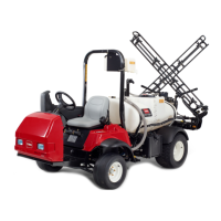
Figure42
1.Frontofthemachine4.Wireharnesstrunk(kit)
2.Cableties5.Hydraulicmotor(right)
3.Hydraulicpump
4.Securethewireharnessofthekittotherear
wireharnessofthemachinewith2cableties
asshowninFigure42.
RoutingtheWireHarnesstothe
CenterSpraySection
1.Routethewireharnessbranchesandtrunkup
atthecenterspraysectionasshowninFigure
43andFigure44.
g208163
Figure43
1.Wireharnesstrunk(kit)3.Hydrauliclter
2.Rearwireharness
(machine)
4.Frontofthemachine
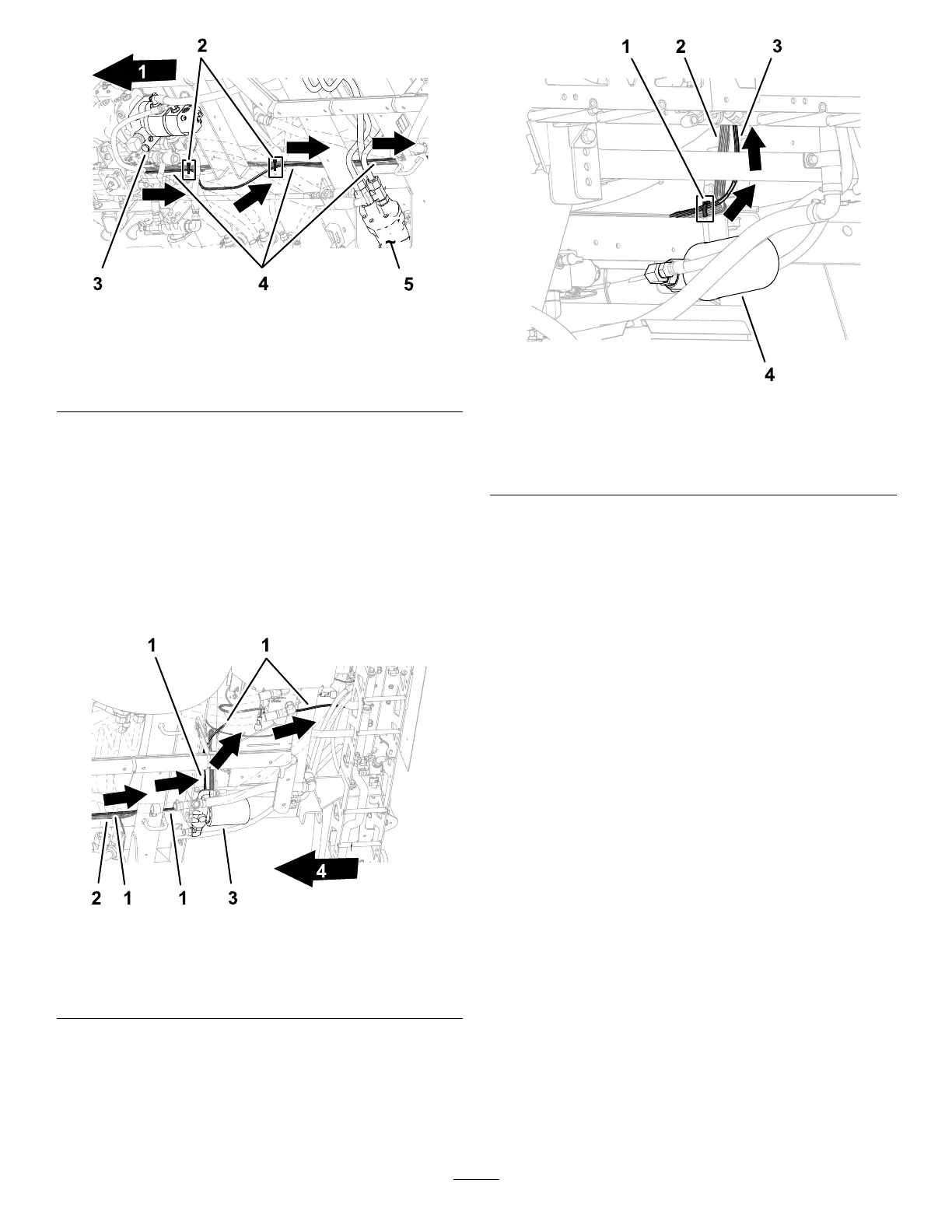
g208165
Figure44
1.Cabletie3.Wireharnesstrunk(kit)
2.Rearwireharness
(machine)
4.Hydrauliclter
2.Securethewireharnessofthekittotherear
wireharnessofthemachinewithacabletieas
showninFigure44.
3.Routethewireharnessofthekittothecenter
spraysection(Figure45)asfollows:
•Thewireharnesstrunkalongthewirestothe
lift-cylindermanifold.
•The89cm(35inches)wireharnessbranch
(withtheelectricalconnectorlabeledLEFT
TURNSIGNAL)towardtheleftendofthecenter
spraysection.
•The71cm(28inches)wireharnessbranch
(withtheelectricalconnectorlabeledRIGHT
TURNSIGNAL)towardtherightendofthe
centerspraysection.
17

 Loading...