Operation
24
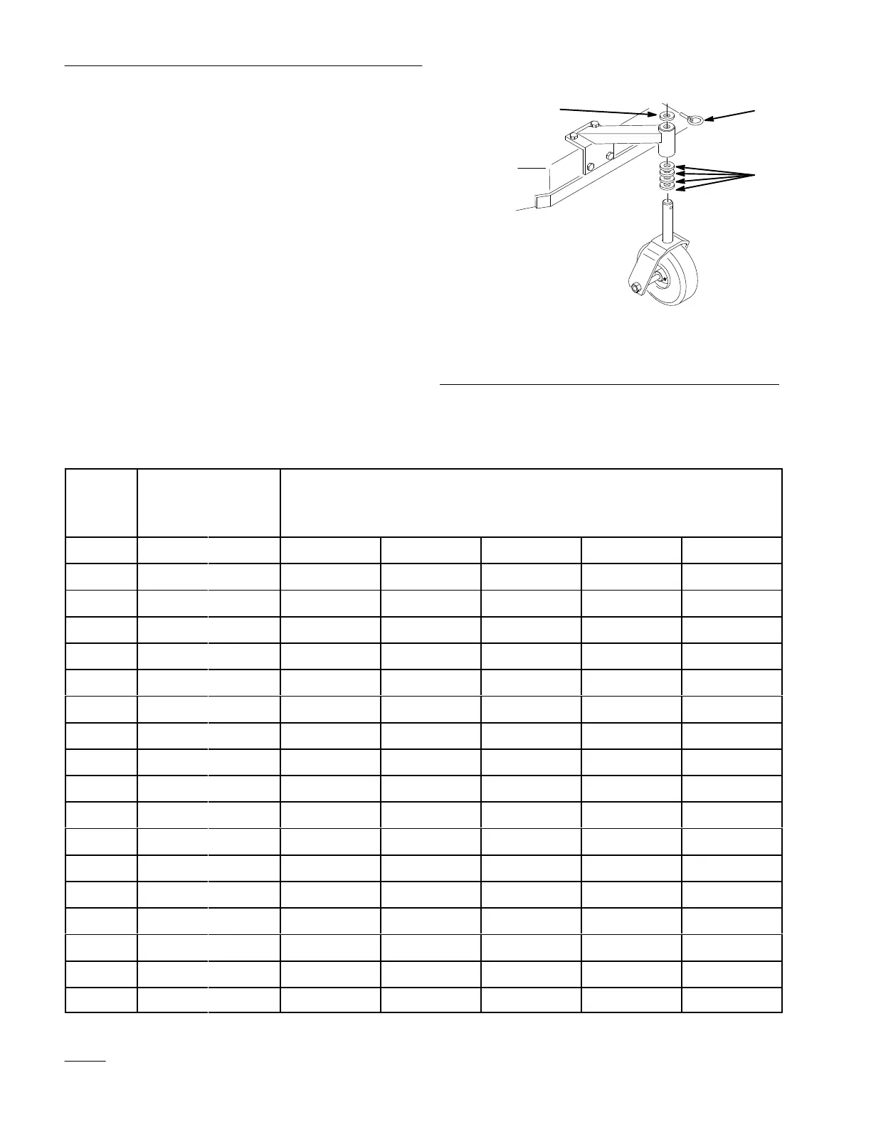
Adjust Caster Position
1. Using the height-of-cut chart, adjust the caster
spacers to match with the axle hole selected
(Fig. 21).
2. Remove clevis pin, slide castor from support and
change spacers(Fig. 21).
3. Install castor in support and insert clevis
pin(Fig. 21).
m–3791
1
3
2
Figure 21
1. Clevis
pin
2.
3/16” (5 mm) spacer
3.
1/2” (13 mm) spacer
Height-of-Cut
Chart
No.
of Spacers
Below Caster
Number of 1/4
″ Blade
Spacers Below
Spindle
x
e
Position
1/2″ 3/16″ 4 3210
A001” 1–1/4” 1–1/2” 1–3/4” 2”
A 0 1 1–1/8” 1–3/8” 1–5/8” 1–7/8” 2–1/8”
A 1 0 1–3/8” 1–5/8” 1–7/8” 2–1/8” 2–3/8”
B 0 1 1–3/8” 1–5/8” 1–7/8” 2–1/8” 2–3/8”
B 1 0 1–5/8” 1–7/8” 2–1/8” 2–3/8” 2–5/8”
B 1 1 1–3/4” 2” 2–1/4” 2–1/2” 2–3/4”
B 2 0 2” 2–1/4” 2–1/2” 2–3/4” 3”
C 1 1 1–7/8” 2–1/8” 2–3/8” 2–5/8” 2–7/8”
C 2 0 2–1/8” 2–3/8” 2–5/8” 2–7/8” 3–1/8”
C 2 1 2–1/4” 2–1/2” 2–3/4” 3” 3–1/4”
C 3 0 2–1/2” 2–3/4” 3” 3–1/4” 3–1/2”
D 2 1 2–3/8” 2–5/8” 2–7/8” 3–1/8” 3–3/8”
D 3 0 2–1/2” 2–3/4” 3” 3–1/4” 3–1/2”
D 3 1 2–3/4” 3” 3–1/4” 3–1/2” 3–3/4”
D 4 0 3” 3–1/4” 3–1/2” 3–3/4” 4”
E 3 1 2–7/8” 3–1/8” 3–3/8” 3–5/8” 3–7/8”
E 4 0 3–1/8” 3–3/8” 3–5/8” 3–7/8” 4–1/8”
E 4 1 3–1/4” 3–1/2” 3–3/4” 4” 4–1/4”
 Loading...