53
4400 Series Installation and Operation Manual – 64527-008
9.5 External Breakers
The UPS is not equipped with isolation circuit breakers. Qualied personnel should provide the external breakers for the AC
input/output, bypass input and DC input.
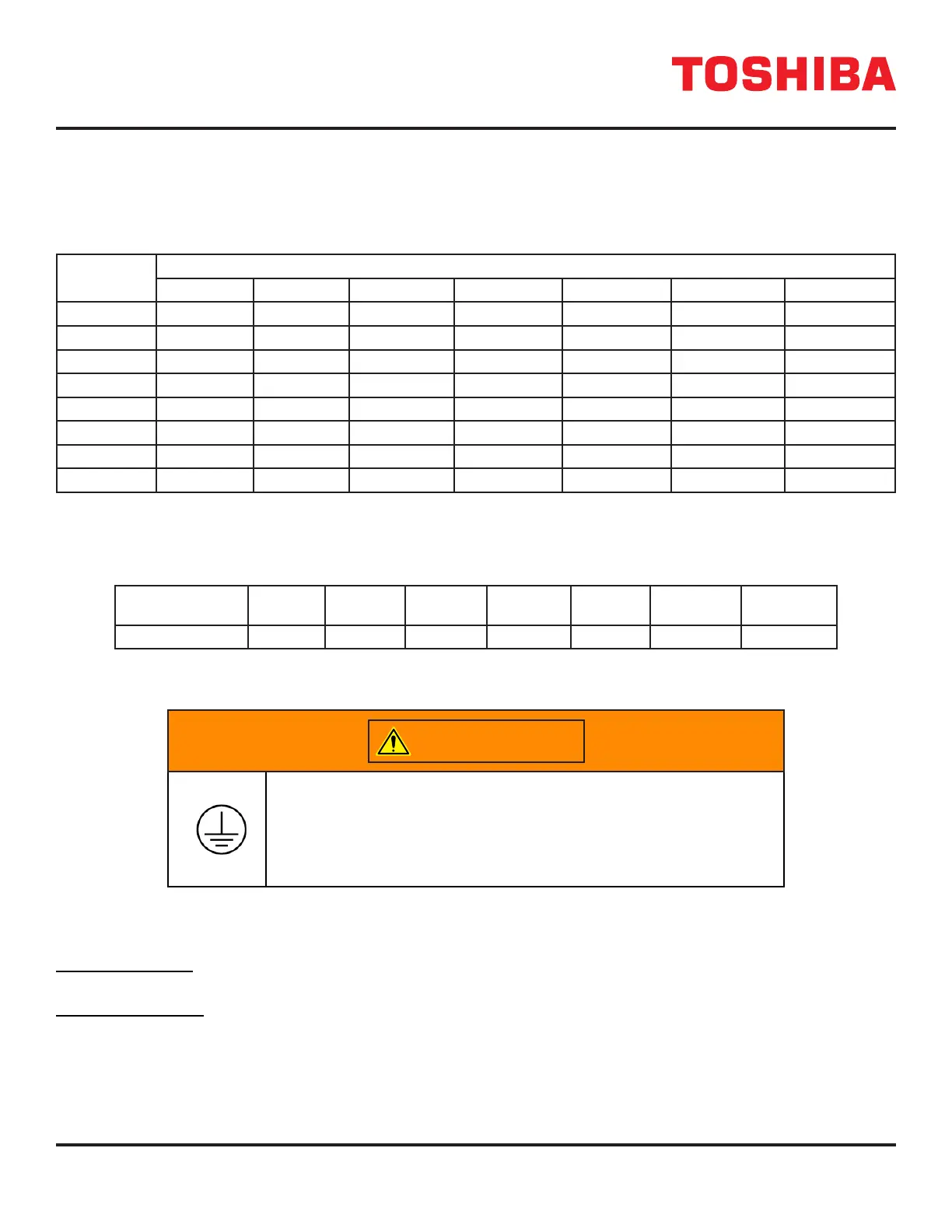
Table 9.4 shows the minimum external breaker rating for each UPS. The bypass, input and output require 3-pole breakers.
TABLE 9.4: UPS MINIMUM BREAKER RATINGS
Voltage
Capacity
15kVA 20kVA 25kVA 30kVA 50kVA 80kVA 100kVA
208/120V 240V/90A 240V/125A 240V/150A 240V/175A 240V/250A 240V/400A 240V/500A
220/127V 240V/90A 240V/125A 240V/150A 240V/150A 240V/250A 240V/400A 240V/450A
240V 240V/80A 240V/100A 240V/125A 240V/150A 240V/225A 240V/350A 240V/400A
380/220V 480V/50A 480V/70A 480V/80A 480V/90A 480V/150A 480V/225A 480V/300A
400/227V 480V/50A 480V/60A 480V/70A 480V/90A 480V/150A 480V/200A 480V/250A
415/240V 480V/45A 480V/60A 480V/70A 480V/80A 480V/125A 480V/200A 480V/250A
480/277V 480V/40A 480V/50A 480V/60A 480V/70A 480V/110A 480V/175A 480V/200A
600V 600V/35A 600V/40A 600V/50A 600V/55A 600V/85A 600V/150A 600V/175A
Note: Above Amp trip ratings are sized for the worst case in the UPS System (Primpary Input Breaker) according to NEC
215.3 guidlines. For more exact recommendations, please refer to “Appendix C – Installation Planning Guide”.
TABLE 9.5: DC (BATTERY) MINIMUM BREAKER RATINGS*
Voltage Capacity
(Min.)
15kVA 20kVA 25kVA 30kVA 50kVA 80kVA 100kVA
500VDC 100A 150A 175A 200A 350A 600A 700A
* For Battery Cabinet Systems not equipped with built-in over-current protection devices.
9.6 Grounding Wire
WARNING
Be sure to
Using the UPS without a proper ground will deteriorate the insulation,
cause leakage of currents and electric shock. The resistance to
ground should be less than or equal to 10 ohms.
The earth grounding bus is located behind the dead front, close to the power lugs. See Section 8.5-8.7. Connect the
grounding wire to the earth ground bus.
The 15-50kVA UPS have a bus strip with 7 (seven) threaded holes for M4 bolts. Use a AWG 2 (or 38 mm
2
) or larger cable
for the grounding wire. Connect the crimp terminal and ground bus together using a M4 bolt.
The 80-100kVA UPS has a ground bus with 10 (ten) M5x0.8 threaded holes, and 6 (six) 0.5118 in (13 mm) unthreaded
holes for 1/2 in bolts. Ground wire must have a crimp terminal with a corresponding diameter bolt hole. Connect the crimp
terminal and ground bus together using the appropriate diameter bolt.
 Loading...