© 2003 - 2008 TOSHIBA TEC CORPORATION All rights reserved e-STUDIO350/352/353/450/452/453
ADJUSTMENT
3 - 89
3
3.12.5 Releasing the stack tray guide lever fixing plate
(1) Remove the right inner cover and the rear cover.
(2) Remove the finisher control PC board, PC board bracket and sensor PC board.
(3) Remove the stack tray.
(4) Remove the stack tray drive unit.
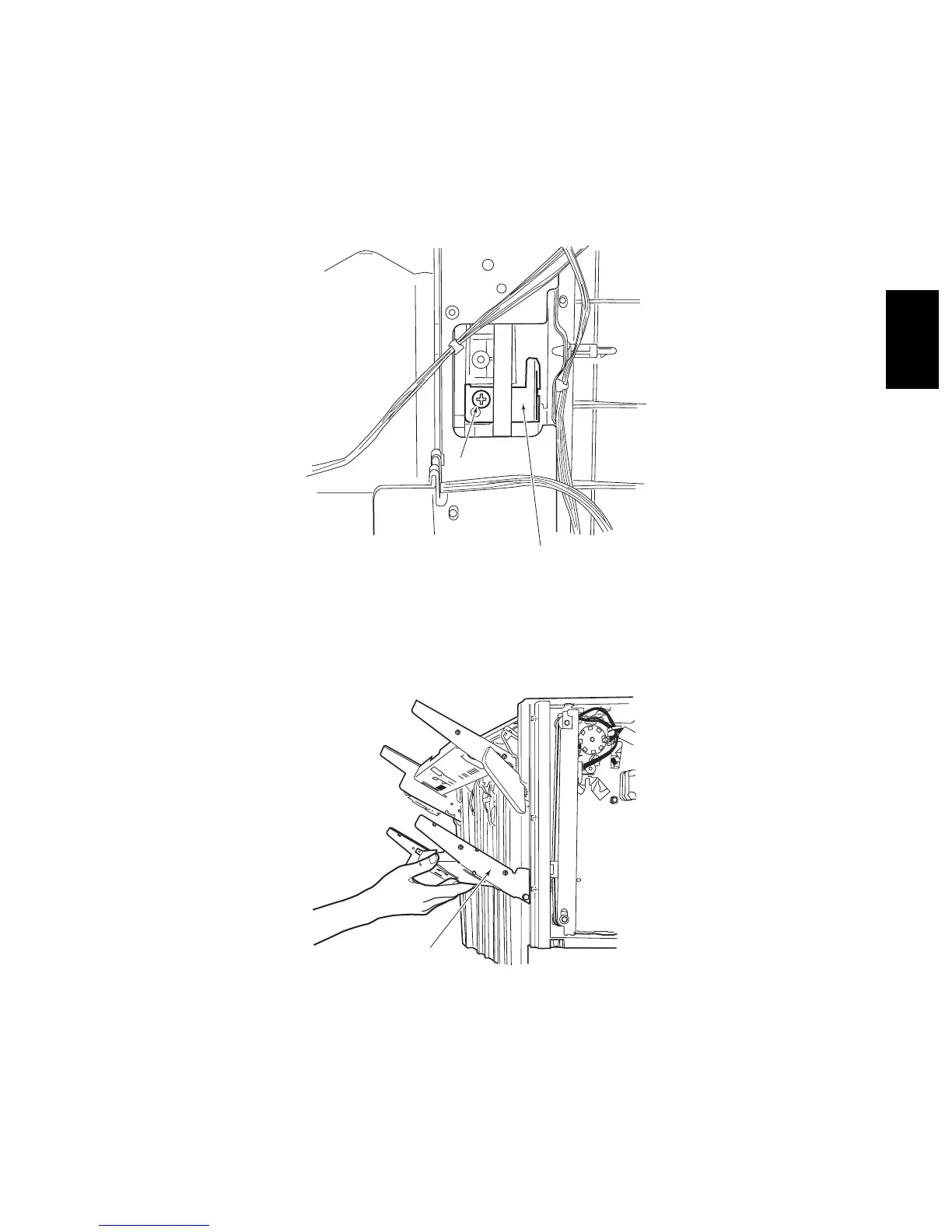
(5) Place the stack tray guide lever fixing plate so that it is in view through the hole in the side plate
(front, rear). Then remove the fixing screw. (Perform the same for the front and the rear.)
Fig. 3-126
Note: Note:
When removing the mounting screw, be sure to hold the stack tray guide lever up from below.
Fig. 3-127
Stack tray guide lever
fixing plate
Screw
Stack tray
guide lever

 Loading...