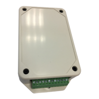
TCS-NET General Purpose Interface
Installation Manual
Toshiba
–21–
EN
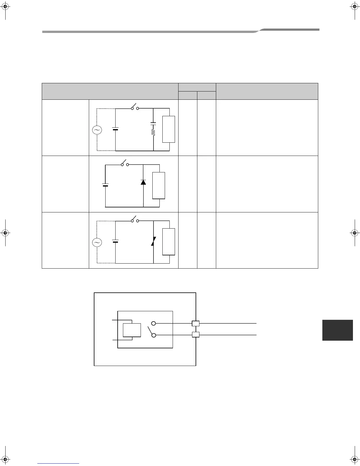
Relay connection
▼ Noise reduction for relay output
When opening/closing a circuit of inductive load, connect a surge killer, diode or varistor in parallel with the load as
shown below.
▼ RO1, RO2, RO3, and RO4 contacts
Contacts are directly output.
Circuit examples
Application
Characteristics
AC DC
Capacitor-resistor
system
Y Y When the load is a relay or solenoid, its
operate time is delayed.
Diode system N Y The operate time is more delayed than the
capacitor-resistor system.
Varistor system Y Y Some operate time is needed.
Inductive load
Inductive load
Inductive load
This product
X1
Relay G5NB 12 V (Omron)
RO1-, RO2-, RO3-, RO4-
RO1+, RO2+, RO3+, RO4+
20-EN
+00DE89308101_01EN_TCB-IFCG10TLE_gene_IM.book Page 21 Monday, December 15, 2008 3:49 PM
 Loading...