EN-5
E6582071
EN
6
6
6
6
6
6
6
6
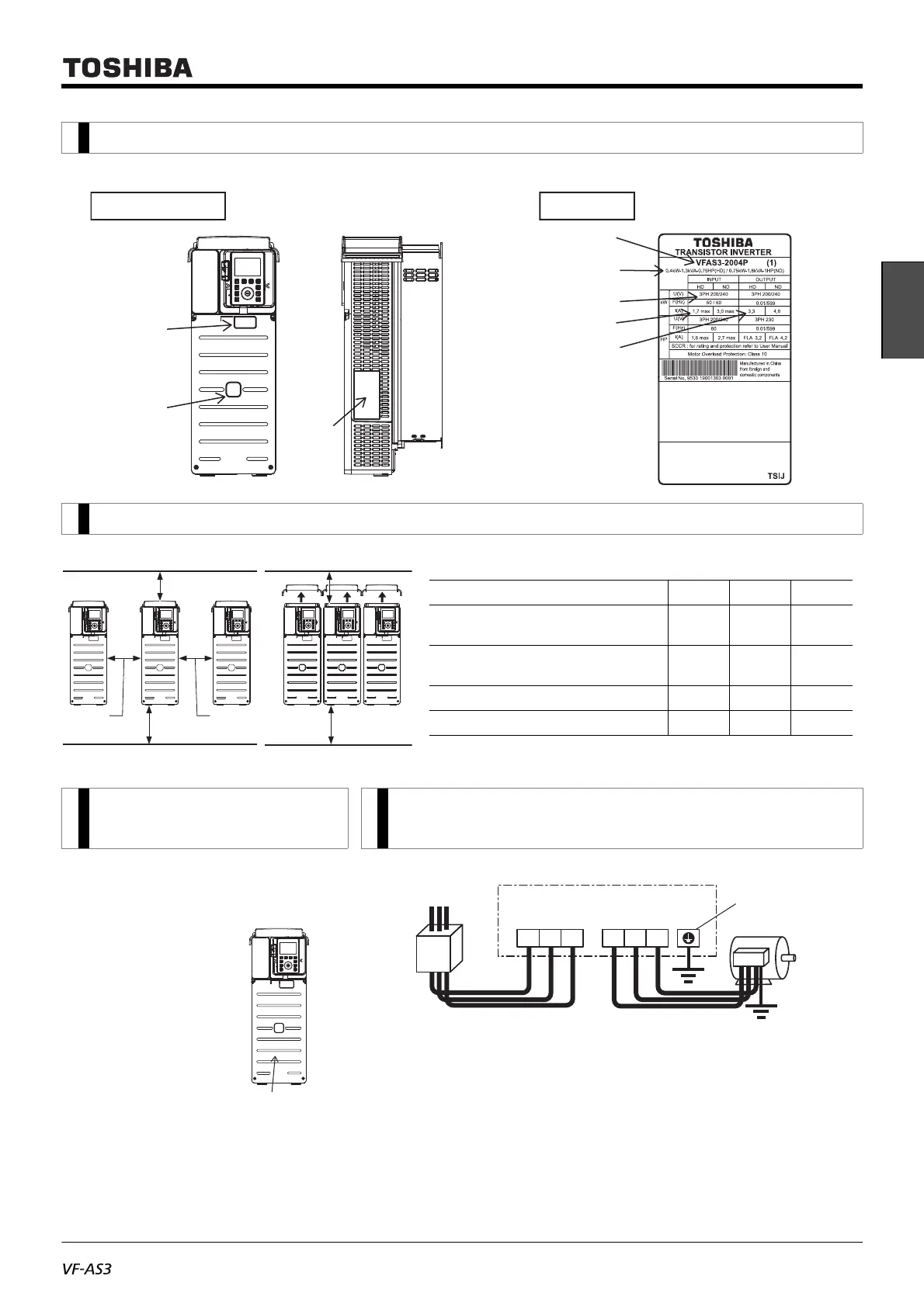
Check that the inverter type is the same as your order.
1. Check the purchase
2. Install the inverter
3. Remove the front
cover
4. Connect to the power supply and the motor
(wiring)
The following shows how to remove
the front cover, e.g. VFAS3-2004P to
2075P. VFAS3-4004PC to 4185PC.
Front cover
(1) Loosen four screws
of the front cover.
(2) Support both sides
of the front cover,
and slide down
slightly.
(3) Lift the front cover,
and remove it from
the unit.
(4) To mount, perform
the procedures in
reverse order.
(1) Connect to the terminal R/L1, S/L2 and T/L3 of the power supply.
(2) Connect to the terminal U/T1, V/T2 and W/T3 of the motor.
Tighten the screws of the power terminal block.
For wiring, follow the wire sizes for each inverter types and wiring
locations shown in the following table.
Inverter main unit
Rating label
Name
plate
Danger label
TOSHIBA INDUSTRIAL PRODUCTS
AND SYSTEMS CORPORATION
Inverter type
Inverter rated
output capacity
Rated voltage
Rated input
current
Rated output
current
Name plate
11 cm
or more
11 cm
or more
H 2 or more
H 1 or more
Basic installation Side-by-side installation
* Remove the top cover.
H 3 or more
H 3 or more
Type-form H1(cm) H2(cm) H3(cm)
VFAS3-2004P - 2370P
VFAS3-4004PC - 4750PC
10 10 10
VFAS3-2450P, 2550P
VFAS3-4900PC - 4132KPC
25 25 25
VFAS3-4160KPC 15 15 25
VFAS3-4200KPC - 4280KPC 20 15 25
* Ground must be
connected securely.
R/L1
Connect the power supply
to [R/L1], [S/L2], and [T/L3].
Connect the motor to [U/T1],
[V/T2], and [W/T3].
Power terminal block
Molded-case
circuit breaker
Power supply
E
Motor
S/L2 T/L3 U/T1 V/T2
W/T3
 Loading...


