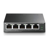
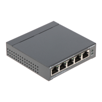
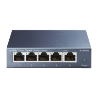
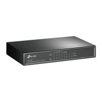
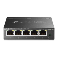
1.1 Wall Mounting Preparation
Before mounting the switch, you need to prepare the tools below:
Ǵ A screw driver.
Ǵ Two screws which complies to the corresponding standard. For details, see Wall
Mounting Specification.
1.2 Wall Mounting Procedure
On the bottom of the panel, there are two mounting holes. You need to drive two screws
into the wall, then mount the switch on the wall. Note that the switch should be mounted
on the wall upright rather than sideways. For TL-SF1008P/TL-SF1008LP/TL-SF1009P/
TL-SG1008P, the switch should be mounted with the ports facing downward and the
LEDs facing upward.
1) Determine the location on the wall where you want to mount the switch.
2) Mark the wall where the two mounting holes are. The distance between the two marks
must be the same as that between the two mounting holes of the switch. For the wall-
mounting-holes distance, see Wall Mounting Specification.
3) Drive the screws into the wall at the marks using the screw driver. For the Screw-
Head-to-Wall Minimum Distance, see Wall Mounting Specification.
4) Mount the switch on the wall.
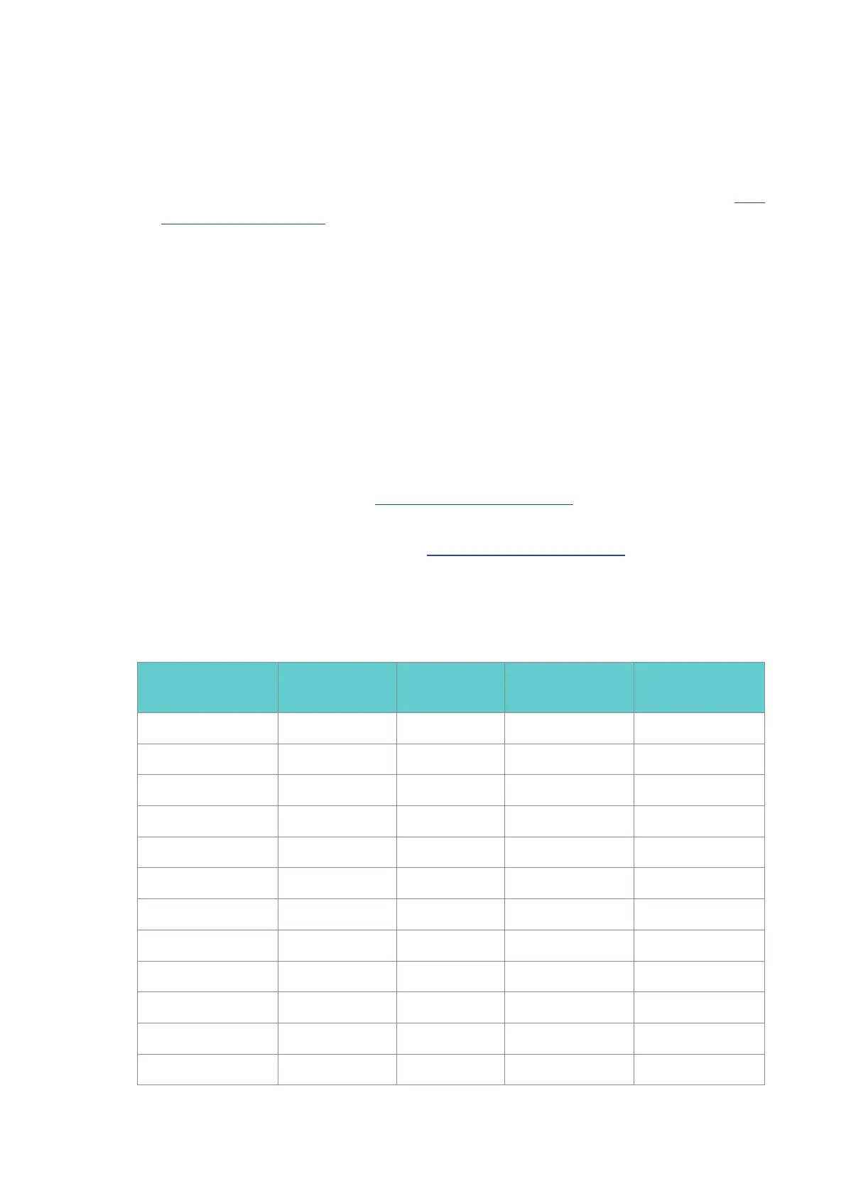
1.3 Wall Mounting Specification
Model
Screw Standard of
ANSI B1.1
Minimum Length
of Screw
Screw-Head-to-Wall
Minimum Distance
Wall-Mounting-Holes
Distance
DS105G
4#, (5#), 6#, 8# 7.5mm
1.5mm 39mm
DS105GE
4#, (5#), 6#
7.5mm
1.5mm 52mm
DS105G-M2 4#, (5#), 6#
7.5mm
1.5mm 52mm
DS105GP
4#, (5#), 6#, 8# 8.5mm
1.5mm 39mm
DS105X 4#, (5#), 6# 7.5mm 1.5mm
150mm
DS106GPP 4#, (5#), 6#, 8# 8.5mm 1.5mm 94mm
DS106P 4#, (5#), 6#, 8# 8.5mm 1.5mm 94mm
DS108G 4#, (5#), 6#, 8# 7.5mm 1.5mm 94mm
DS108GE 4#, (5#), 6# 7.5mm 1.5mm 110mm
DS108G-M2 4#, (5#), 6# 7.5mm 1.5mm 110mm
DS108GP
4#, (5#), 6#, 8#
8.5mm 1.5mm 94mm
DS110GMP 4#, (5#), 6# 8.5mm 1.5mm
150mm

 Loading...