ALL phases of this installation must comply with NATIONAL, STATE AND LOCAL CODES
IMPORTANT — This Document is customer property and is to remain with this unit. Please return to service information
pack upon completion of work.
Installer’s Guide
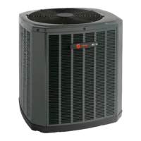
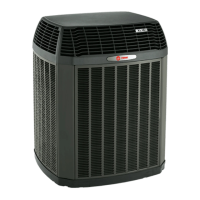
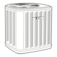
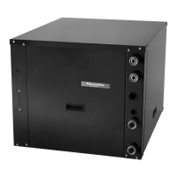
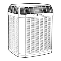
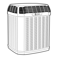
Condensing Units
2TTX4018-060 & 2TTX5024-048
These instructions do not cover all variations in
systems nor provide for every possible contingency to
be met in connection with installation. All phases of
this installation must comply with NATIONAL, STATE
AND LOCAL CODES. Should further information be
desired or should particular problems arise which are not
covered sufficiently for the purchaser’s purposes, the matter
should be referred to your installing dealer or local distributor.
A. GENERAL
The following instructions cover 2TTX4 & 2TTX5; Condens-
ing Units.
NOTE:
The 2TTX4 outdoor units, except 2TTX4060, may be used
with indoor units equipped with Thermostatic Expansion
Valve or Accutron™ Flow Control Check Valve (F.C.C.V.)
assembly for refrigerant flow control only. The 2TTX5, and
2TTX4060 outdoor units must be used with indoor units
equipped with Thermostatic Expansion Valve only.
Check for transportation damage after unit is uncrated.
Report promptly, to the carrier, any damage found to the
unit.
To determine the electrical power requirements of the unit,
refer to the nameplate of the unit. The electrical power
available must agree with that listed on the nameplate.
B. LOCATION & PREPARATION
OF THE UNIT
1. When removing unit from the pallet, notice the tabs on
the basepan. Remove tabs by cutting with a sharp tool as
shown in Figure 2 (see page 2).
2. The unit should be set on a level support pad at least
as large as the unit base pan, such as a concrete slab.
If this is not the application used please reference
“XLi-APG**-EN” (* latest revision number).
3. The support pad must NOT be in direct contact with any
structure. Unit must be positioned a minimum of 12"
from any wall or surrounding shrubbery to insure
adequate airflow. Clearance must be provided in front
of control box (access panels) & any other side requiring
service access to meet National Electrical Code. Also,
the unit location must be far enough away from any
structure to prevent excess roof run-off water from
pouring directly on the unit. When choosing the location
of the unit(s), sound transmission through air and
1
refrigerant lineset should be taken into consideration. It
is recommended to locate unit(s) away from areas
(bedrooms, etc.) where such sound will be objectionable.
4. The top discharge area must be unrestricted for at least
five (5) feet above the unit.
5. When the outdoor unit is mounted on a roof, be sure the
roof will support the unit’s weight. Properly selected
isolation is recommended to prevent sound or vibration
transmission to the building structure.
6. The maximum length of refrigerant lines from outdoor to
indoor unit should NOT exceed sixty (60) feet.
7. If outdoor unit is mounted above the air handler, maxi-
mum lift should not exceed sixty (60) feet (suction line).
If air handler is mounted above condensing unit, maxi-
mum lift should not exceed sixty (60) feet (liquid line).
NOTE:
Refer to “Refrigerant Piping Software” Pub. No. 32-3312-0*,
and “Refrigerant Piping Manual” Pub. No. 32-3009-0* (the
position of the * denotes latest revision number).
8. Locate and install indoor coil or air handler in accor-
dance with instruction included with that unit.
5 FT. ABOVE UNIT-UNRESTRICTED
18-AC54D1-4