12 18-AC79D1-6-EN
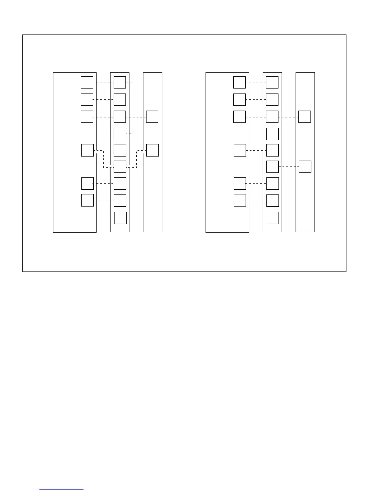
11.2 Low Voltage Hook-up Diagrams
With TEM 3, 4, 6With TAM 4, 5, 7
• Units with pigtails require wirenuts for connections. Cap all unused wires.
• For any BK enabled comfort control, do not connect Y1 or Y2 at the air handler.
•
In AC systems for multiple stages of electric heat, jumper W1 and W2 together if comfort control has only one stage of heat.
* Y for TEM3 and TEM4
** Only applies for TEM6
Thermostat Air Handler
Outdoor
Unit
R
G
B
W1
W2
B
Y
R
G
B/C
Y
W1
W2
Blue
24 VAC HOT
FAN
24 VAC
Common
SOV
COOL/HEAT
1st STAGE
HEATING
2nd STAGE
EMERGENCY
HEAT
Pink
White
O
Y1
Y2
*
BK
WH/BLK
Thermostat Air Handler
Outdoor
Unit
R
G
B
W1
W2
B
R
G
B/C
Y
l
W1
W2
Blue
24 VAC HOT
FAN
24 VAC
Common
SOV
COOL/HEAT
1st STAGE
HEATING
2nd STAGE
EMERGENCY
HEAT
Pink
White
O
Y
l
Y
O
Y
O
BK
WH/BLK
**
 Loading...