18 18-AC123D1-1B-EN
Weigh-In Method can be used for the initial
installation, or anytime a system charge is being
replaced. Weigh-In Method can also be used
when power is not available to the equipment
site or operating conditions (indoor/outdoor
temperatures) are not in range to verify with the
subcooling charging method.
14.3 Weigh-In Method for Charging
Indoor Wet Bulb Temp (F)
Outdoor
Dry
Bulb
Temp.
(F)
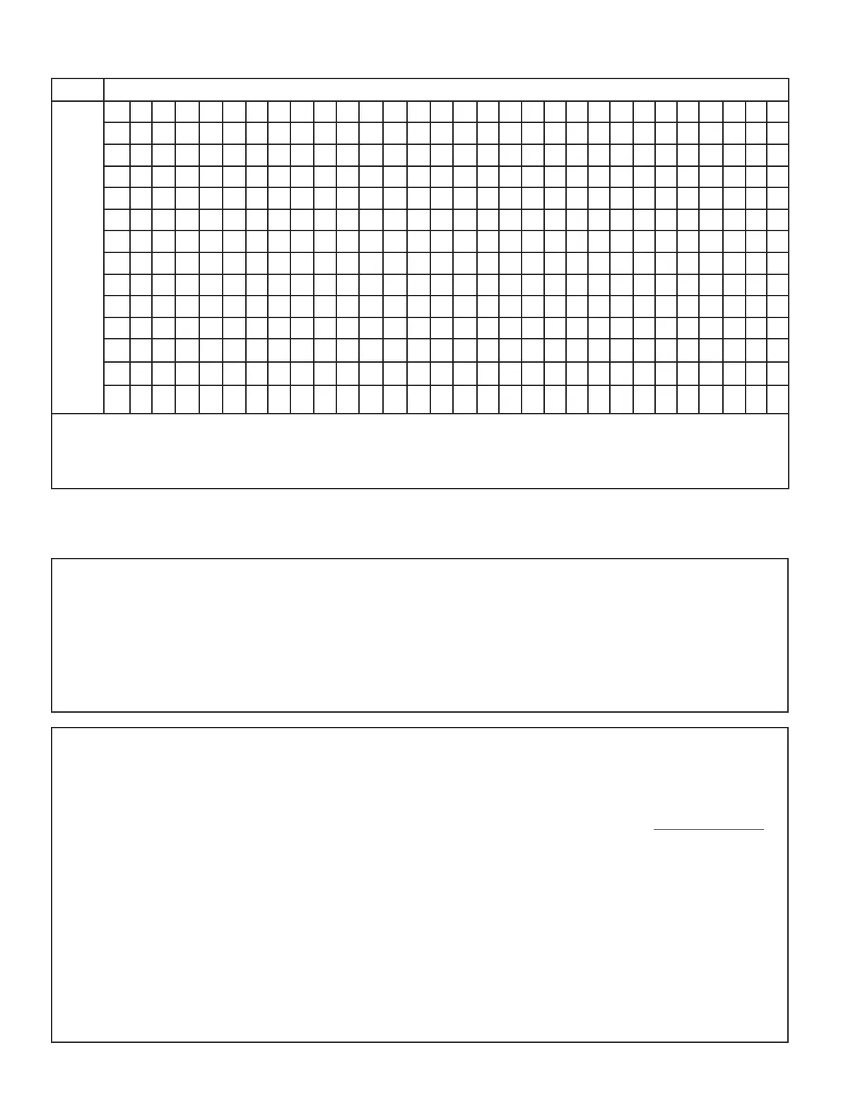
50 51 52 53 54 55 56 57 58 59 60 61 62 63 64 65 66 67 68 69 70 71 72 73 74 75 76 77 78
55 7 9 10 11 12 14 15 17 18 20 21 23 24 26 27 29 30
60 5 7 8 9 10 12 13 15 16 18 19 21 22 24 25 27 28 30 31
65 4 6 8 10 11 13 14 16 17 18 19 21 22 24 25 27 28 27 31
70 5 7 8 10 11 13 14 16 17 18 19 21 22 24 25 27 28 30 31
75 5 6 7 9 10 12 14 16 18 19 21 22 24 26 28 29 31 32
80 4 6 7 9 10 11 12 14 16 18 19 21 23 25 26 28 29 31 33
85 4 6 7 9 10 13 14 16 18 20 21 23 24 26 28 29 30 31 32
90 4 6 8 10 11 13 14 16 18 20 22 24 25 27 28 30 31
95 4 6 8 10 13 14 16 18 20 22 23 25 26 28 29
100 6 8 10 12 13 16 18 20 21 23 25 27 29
105 4 6 7 9 11 13 15 18 20 22 24 26 28
110 4 7 9 11 13 16 18 21 23 26 28
115 6 9 12 14 16 19 21 24 26
Using a digital psychrometer, measure the return air wet-bulb temperature at the unit just before the coil. Also measure the outdoor dry-bulb tem-
perature. Use these temperatures to locate the target superheat on the charging table. Do not attempt to charge the system if these conditions fall
outside of this charging table.
ADD refrigerant to DECREASE total superheat. REMOVE refrigerant to INCREASE total superheat. Always allow 10 to 15 minutes of operature
after any refrigerant or air flow change prior to determining the final superheat.
Fixed Orifice Superheat Charging Table
Calculating Charge Using the Weigh-In Method
STEP 1 - Measure in feet the distance between the
outdoor unit and the indoor unit and record on Line 1.
Include the entire length of the line from the service
valve to the IDU.
STEP 2 - Enter the charge multiplier (0.6 oz/ft). Each
linear foot of interconnecting tubing requires the
addition of 0.6 oz of refrigerant.
STEP 3 - Multiply the total length of refrigerant tubing
(Line 1) times the value on Step 2. Record the result
on Line 3 of the Worksheet.
STEP 4 - This is the amount of refrigerant to weigh-in
prior to opening the service valves.
1. Line length (ft) ______________
2. Charge multiplier x ____ 0.6 ______
3. Step 1 x Step 2 = _____________
4. Refrigerant = _____________
 Loading...