18-AC98D1-7D-EN 5
Section 4. Setting the Unit
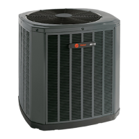
4.1 Pad Installation
When installing the unit on a support pad, such
as a concrete slab, consider the following:
• The pad should be at least 1” larger than the
unit on all sides.
• The pad must be separate from any structure.
• The pad must be level.
• The pad should be high enough above grade
to allow for drainage.
• The pad location must comply with National,
State, and Local codes.
4TTR6018J 3/4 3/8 3/4 3/8 150 50
4TTR6024J 3/4 3/8 3/4 3/8 150 50
4TTR6030J 3/4 3/8 3/4 3/8 150 50
4TTR6035J 3/4 3/8 3/4 3/8 150 50
4TTR6036J 7/8 3/8 3/4 3/8 150 50
4TTR6041J 7/8 3/8 3/4 3/8 150 50
4TTR6042J 7/8 3/8 7/8 3/8 150 50
4TTR6048J 7/8 3/8 7/8 3/8 150 50
4TTR6049J 7/8 3/8 7/8 3/8 150 50
4TTR6060J 1-1/8 3/8 7/8 3/8 150 50
4TTR6060K 1-1/8 3/8 7/8 3/8 150 50
4TTR6061C 1-1/8 3/8 7/8 3/8 150 50
Section 5. Refrigerant Line Considerations
5.1 Refrigerant Line and Service Valve Connection Sizes
Table 5.1
Line Length
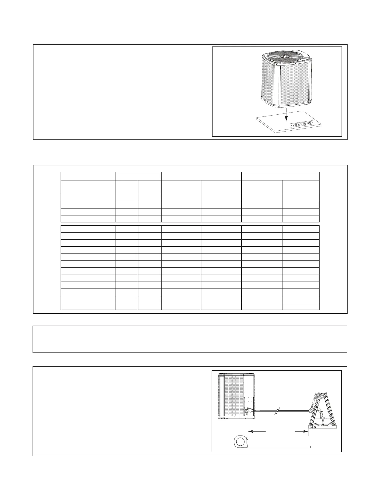
5.3 Required Refrigerant Line Length
5.2 Factory Charge
Determine required line length and lift. You will
need this later in STEP 2 of Section 14.
Total Line Length = __________ Ft.
Total Vertical Change (lift) = __________ Ft.
The outdoor condensing units are factory charged with the system charge required for the outdoor condensing
unit, ten (10) feet of tested connecting line, and the smallest rated indoor evaporative coil match. Always verify
proper system charge via subcooling (TXV/EEV) or superheat (fixed orifice) per the unit nameplate.
Line Sizes Service Valve Connection Sizes
Max Line & Lift Lengths
Model
Vapor
Line
Liquid
Line
Vapor Line
Connection
Liquid Line
Connection
TOTAL Max
Line Length (ft.)
Max Lift (ft.)
4TTR6024N 3/4 3/8 3/4 3/8 150 50
4TTR6036N 3/4 3/8 3/4 3/8 150 50
4TTR6048N 7/8 3/8 7/8 3/8 150 50
4TTR6060N 1-1/8 3/8 7/8 3/8 150 50
 Loading...