RT-SVX060D-GB
18
4 UNT-PRC002-GB
Technical Data
FWD 08 12 20 30 45
Power supply (V/Ph/Hz) 230/1/50
Capacities
Cooling capacity on water (1) (kW) 5,2 8,3 15 18,8 30,1
Heating capacity on water (2) (kW) 6,3 11,9 18,9 20,9 38,2
Fan motor (type) 2 x direct drive centrifugal
Fan power input (3) (kW) 0,23 0,46 0,65 1,04 1,51
Current amps (3) (A) 1,1 2,2 3,1 4,7 5,5
Start-up amps (A) 3,2 5,5 9,3 14,1 16,5
Air flow
minimum (m
3
/h) 490 980 1400 1800 2700
nominal (m
3
/h) 820 1650 2300 3000 4500
maximum (m
3
/h) 980 1970 2600 3600 5400
Main coil
Water entering/leaving connections (type) ISO R7 rotating female
(Dia) 3/4" 3/4" 1 1/2" 1 1/2" 1 1/2"
Electric heater (accessory for blower only)
Electric power supply (V/Ph/Hz) 230/1/50 230/1/50 or 400/3/50 400/3/50 400/3/50 400/3/50
Heating capacity (kW) 2/4 8 10 12 12
Hot water coil (accessory for blower only)
Heating capacity (4) (kW) 6,3 12 17,4 22,4 34,5
G2 filter (filter box accessory)
Quantity 2 2 2 2 2
Dimensions ( LxWxth) (mm) 386x221x8 486x271x8 586x321x8 586*421*8 586*621*8
G4 filter (filter box accessory)
Quantity - 2 2 2 2
Dimensions ( LxWxth) (mm) - 486x264x48 586x314x48 586*414*48 586*614*48
Condensate pump (accessory) (type) Centrifugal
Water flow - lift height (l/h - mm) 24 - 500
Not available for FWD30 and FWD45
Sound level (L/M/H speed)
Sound pressure level (5) (dB(A)) 36/40/43 38/41/44 46/50/53 47/52/57 47/52/58
Sound power level (5) (dB(A)) 46/50/53 48/51/54 56/60/63 57/62/67 57/62/68
Unit dimensions
Width x Depth (mm) 890 x 600 1090 x 710 1290 x 820 1290 x 970 1290 x 1090
Height (mm) 250 300 350 450 650
Shipped unit dimensions
Width x Depth (mm) 933 x 644 1133 x 754 1333 x 864 1333 x 1008 1333*1133
Height (mm) 260 310 360 460 660
Weight (kg) 32 46 61 76 118
Colour galvanised steel
Recommended fuse size
Unit alone (aM/gI) (A) 8/16 8/16 8/16 8/25 8/25
Unit with electric heater (gI) (A) 16 (2kW),25 (4kW) 40 (230V),3*16 (400V) 3*20 3*25 3*25
(1) Conditions: Water entering/leaving temperature: 7/12 °C, Air inlet temperature 27/19°C DB/WB - Nominal air flow
(2) Conditions: Water entering/leaving temperature: 50/45 °C, Air inlet temperature 20°C DB - Nominal air flow
(3) At high speed with nominal air flow.
(4) Water entering/leaving temperature 90/70 °C, air inlet temperature 20 °C DB, Nominal air flow.
(5) A rectangular glass wool duct 1m50 long is placed on the blower.The measurement is taken in the room containing the blower unit.
Heat exchanger operating limits:
FWD:
*water temperature: max 100° C
*absolute service pressure: min 1 bar/max 11 bars
Accessories - Hot water coil:
*water temperature: min. +2° C/max. 100° C
*absolute service pressure: min 1 bar/max 11 bars
General information: The installation must conform to all
local standards and regulations.
Reception of Units
Unit Handling
The unit is supplied on wooden blocks. It is
recommended to check the machine’s condition upon
reception.
There are two ways to handle the unit:
1) Handle the machine using a forklift, in accordance
with applicable safety regulations. Handling of the
unit is prohibited unless forks are longer than the
length of the unit.
2) Use a lifting beam correctly adjusted to t the unit.
The units are supplied on the truck but are not
unloaded. A lifting lug is provided on each corner of the
unit’s base to facilitate handling. 4 shackles and 4 slings
are required.
Use a lifting beam to prevent the cables pressing too
hard on top of the unit during lifting.
Important: For unit to t on the roof curb the wooden
blocks must be removed.
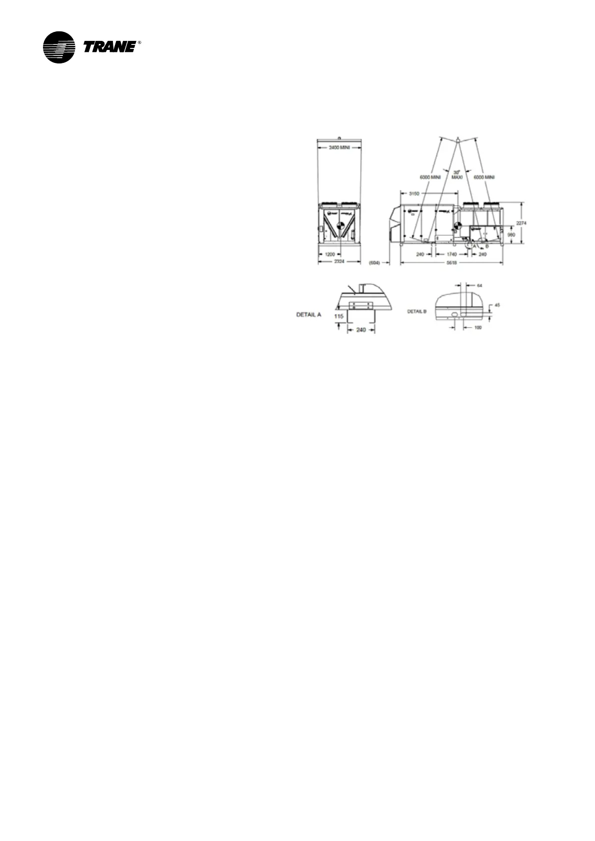
Lifting and moving Instructions
It is recommended to use the special built-in rigging
points shown in the diagram and the following
instructions:
1 - Detailed lifting instructions will be shared along with
unit documentation package.
2 - Use the four rigging points which are built into the
unit.
3 - Slings and a spreader bar are to be provided by the
rigger.
4 - The minimum lifting capacity of each sling (with an
angle of 30° max) as the spreader bar must be equal
or higher than tabulated unit shipping weight.
5 - Caution : This unit must be lifted and handled with
care. Avoid shocks while handing.
Figure 2 - Schematic
of
Lifting drawing
Roof Curb Installation
Roof curb option is not developed by Trane. However it
is possible to use specic roof curb developed case by
case for down ow units. The roof curb should support
the unit and should ensure water tightness.
Installation
 Loading...
