Installation
CLCH-SVN05C-EN 11
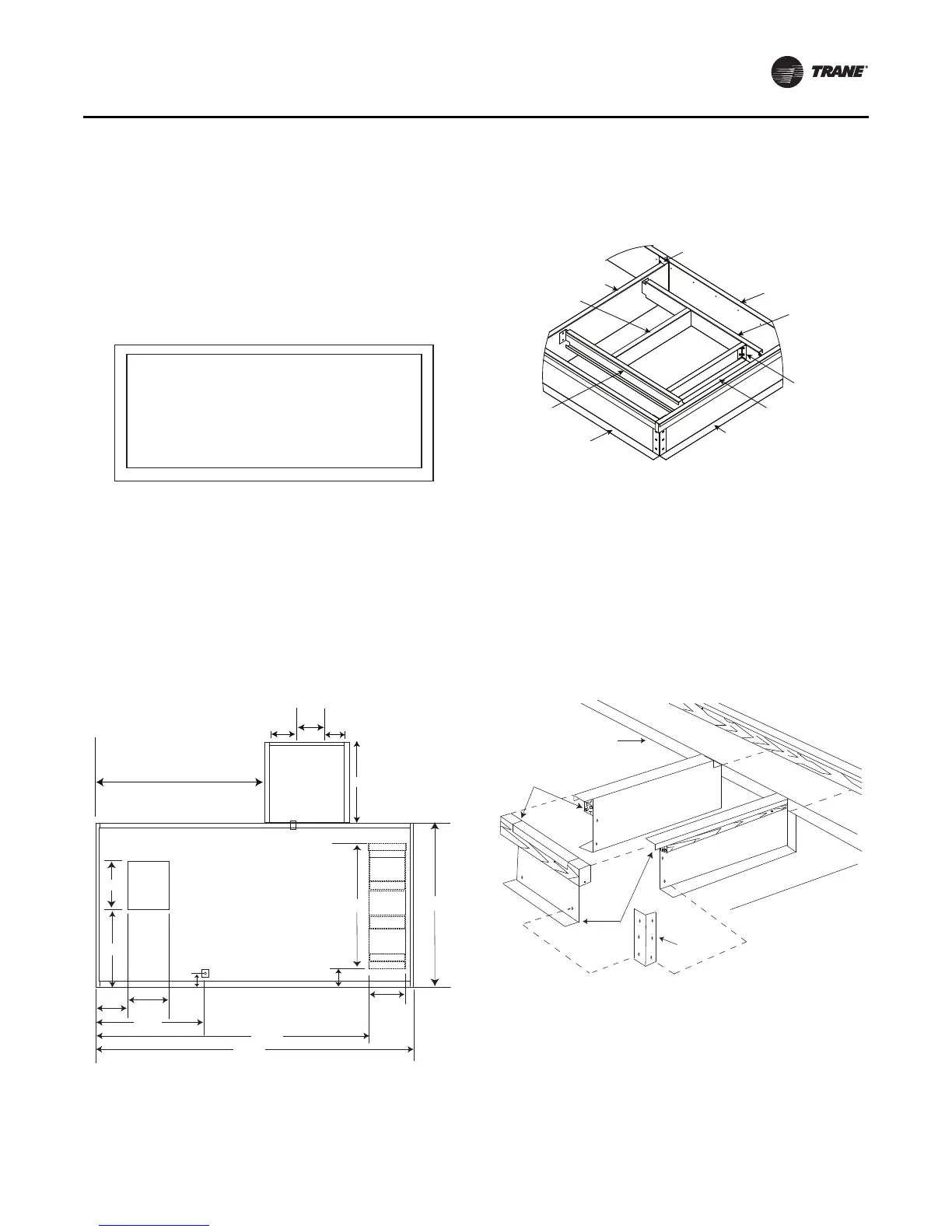
Check curb dimensions for squareness as shown in the
figure below. Measurements from A-B should equal
measurement from C-D (± 1/8-inch).
Note: Measurements A-C, D-B, A-D, and B-C are inside
curb dimensions and are supplied with the unit-
specific roof curb manual.
3. Tighten nuts/bolts at all locations. Ensure lock nuts are
securely tightened.
4. Review the details curb plan view as-built to determine
the location of the supply and/or return openings and
placement of duct support members. See figure below.
5. Attach duct support members to each side of roof curb
perimeter wall with self-drill screws. See figure below.
6. Assemble the pipe cabinet roof curb (when supplied).
See the figure below.
Note: If pipe cabinet roof curb interferes with splice
plates, field drill holes to match those in the splice
plate. Attach the pipe cabinet roof curb with splice
plate bolts. Self-drill the other end.
7. Install gasket along the perimeter of the pipe chase
roof curb and unit roof curb. Gasketing is provided
with the roof curb when ordered from Trane.
8. Install the curb. The curb may be set on structural
framing (by others). This curb is designed to transfer
the load to a continuous underlying structural frame.
The structural members (by others) should span the
perimeter of the curb.
Figure 12. Unit roof curb perimeter
Figure 13. Typical as-built curb detail plan view (inches)
from submittal package
79
61 1/4
8 7/8
17 3/4
38
13 1/2
14
9 1/2
23 1/8
37 7/8
5 1/2
15 7/8
19 7/8
55 5/8
134 1/4
155 7/8
75 1/2
Figure 14. Duct support detail
Figure 15. Pipe cabinet roof curb assembly
Note: Open side of 1301 crossbrace
must face to the left.
Notes:
1. 1306-xx (PTAF duct support) is field cut to length.
2. Use self drillers (included) to attach 1307-xx (duct
support angle) to 1305-xx and 1606-xx.
1307-01
1305-01
1384-01
1301-01
1306-02
1305-02
1384-02
1385-01
1306-01
Unit roof curb
2 x 4 nailer
Pipe chase
roof curb
Roof curb
angle
 Loading...


