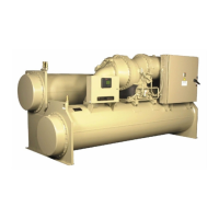
Refer to the Mechanical and Electrical sections of this manual for detailed instruc-
tions.
-
sors, flow sensors or other factoryordered field-installed options, as required. Loose
parts are located in the starter panel if equipped with a unit-mounted starter. If not
equipped with a unit-mounted starter, loose parts are shipped in the motor junction
box.
and of sufficient strength and mass to support the chiller operating weight. Place the
manufacturersupplied isolation-pad assemblies under the unit.
Note: Field piping must be arranged and supported to avoid stress on the equipment.
It is strongly recommended that the piping contractor provide at least 3 feet (914 mm)
of clearance between the preinstallation piping and the planned location of the unit.
This will allow for the proper fit upon arrival of the unit at the installation site. All nec-
essary piping adjustments can be made at that time.
-
stream of the evaporator and condenser water boxes, in order to isolate the shells for
maintenance and to balance and trim the system.
-
ing and the condenser-water piping. Interlock each switch with the proper pump start-
er, to ensure that the unit can only operate when water flow is established.
Note: reference graphs 1-16 in the Installation Mechanical section for proper water
flow.
-
ter piping, adjacent to the inlet and outlet connections of both the evaporator and the
condenser.
-
ulating valves.
the atmosphere.
(75 psig = 517 kPa maximum) for leak testing.
completed.
CVGF-SVX03B-EN
19
General Information

 Loading...