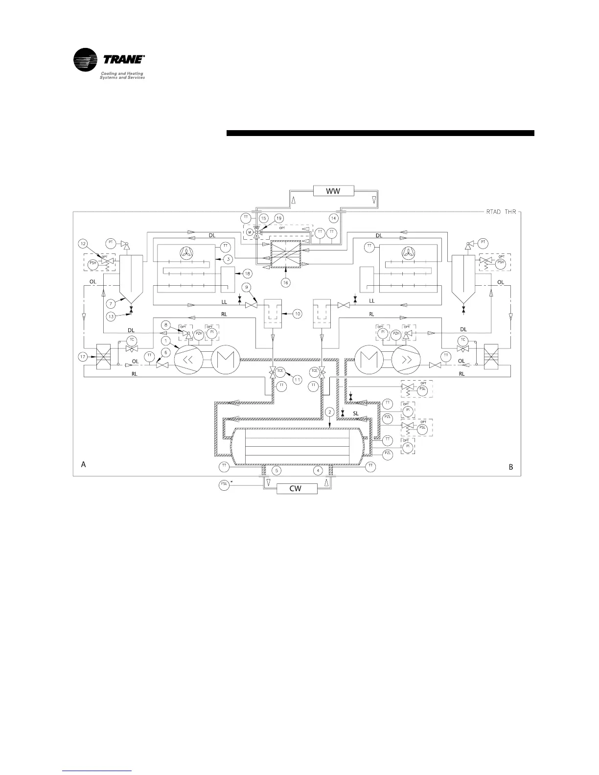
1 = Screw compressor
2 = Evaporator
3 = Air-cooled condenser
4 = Evaporator water inlet connection
5 = Evaporator water outlet connection
6 = Oil service valve
7 = Oil separator
8 = Discharge service valve
9 = Liquid shutoff valve
10 = Filter drier
11 = Electric expansion valve
12 = Relief valve
13 = Service valve
14 = 3-way valve
PI = Gauge
PT =Pressure transducer
PSH = High pressure relief valve
PSL = Low pressure relief valve
PZH = High pressure switch
PZL = Low pressure switch
TT = Temperature sensor
TCE = Electric expansion valve
OPT = Option
DL = Discharge line
SL = Suction line
LL = Liquid line
RL = Auxiliary oil cooler refrigerant line
A = Circuit A
B = Circuit B
LA only = Low or wide ambient
temperature only
FSL = Flow switch
 Loading...
