Installation
42 SO-SVN048A-EN
Drive Installation – Pedestal
Mount (All Kits)
Important:
• For wall mount option, follow instructions for remote wall in
TR200 New D-Frame, 110–400kW Operating Instructions
(BAS-SVX54*-EN).
• See “Drive Dimensions,” p. 15 and “Pedestal Drawings,”
p. 17or drive mounting dimensions.
• See Figure 8, p. 15 or Figure 10, p. 16 for wall mount
dimensions.
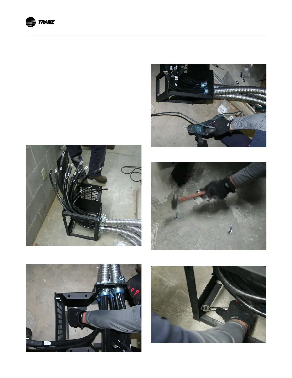
1. Determine the desired location for the drive and position
the pedestal in place.
2. Temporarily route power wire conduit to desired drive
pedestal location to check for any routing issues.
3. Mark the locations for the anchor bolts using the bottom
slots of the pedestal for a template.
4. Drill the four required holes for the anchor bolts and install
the 3/8-inch anchor bolts.
Figure 53.
Figure 54.
Figure 55.
Figure 56.

 Loading...


