BAS-SVX46E-EN
15
• A PM014 power supply module is required for applications that require more than two XM30/
XM32 expansion modules.
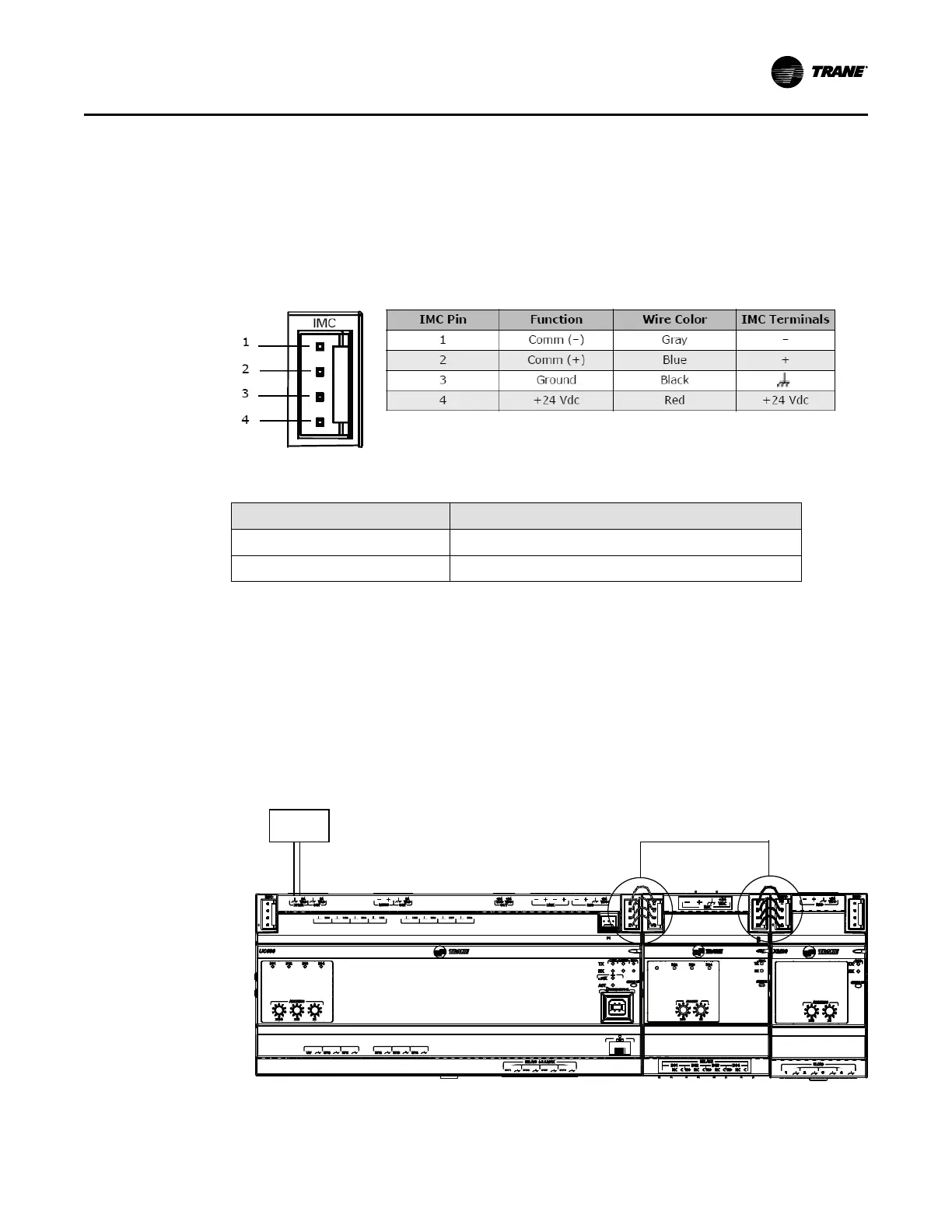
IMC Harness Pins
The IMC harness connector provides communication and power among devices on a link. It is
important to know the function for each of the IMC pins. In some cases, the red +24 Vdc wire that
provides power may need to be removed.
Figure 6. IMC Harness Pins
Table 8. IMC harness part numbers
Part Number
Description
X19070636020
Cable, wire harness double housing 3 cond., 18 AWG
X19070636010
Cable, wire harness double housing 4 cond., 18 AWG
Communication Wiring Examples
Figure 7, p. 15 illustrates an example of a typical installation where the IMC harness/IMC
terminals provide both 24 Vdc power and IMC communications.
• The UC600 is powered by the 24 Vac input (provided by the UL-listed transformer).
• The XM30 and XM32 are powered by 24 Vdc through the IMC link that is connected to the
UC400/UC600.
Figure 7. Example of a typical installation: two expansion modules and one UC600
controller
A
O
6
UI
14
A
O
5
UI
13
A
O
4
UI
12
A
O
3
UI
11
A
O
2
UI
10
A
O
1
UI
9
B
O
4
B
O
3
B
O
2
B
O
1
RELAYS
0
.
5
A MAX
IM
C
1
IM
C
P
1
UI
8
UI
7
UI
6
UI
5
UI
4
UI
3
UI
2
UI
1
IMC
+
24
VDC
LINKOUT
+
24
VDC
+
24
VDC
OUT
24
VAC
MBUS
OUT
24
VAC
XFMR
24
VAC
SERVICE TOOL
SERVI
C
E
LINK
ACT
IM
C
MBUSLINK
RX
TX
U
C
600
ADDRESS
0
1
2
3
4
5
6
7
8
9
x1
0
1
2
3
4
5
6
7
8
9
x10
0
1
2
3
4
5
6
7
8
9
x100
B
O
4
B
O
3
B
O
2
B
O
1
TRANE
XM 32
BO1 BO2 BO3 BO4
ADDRESS
x10
x1
1
2
3
4
5
6
7
8
9
0
1
2
3
4
5
6
7
8
9
0
IMC
SERVICE
RX
TX
RELAYS
BO1 BO2
BO3 BO4
NO NC C NO NC C NO NC C NO NC C
1
A B
IMC
+24
VDC
ADDRESS
0
1
2
3
4
5
6
7
8
9
x1
0
1
2
3
4
5
6
7
8
9
x10
432
1
UI / AO
I
M
C
1
I
M
C
IMC
+
24
VD
C
SERVI
C
E
IM
C
RX
TX
XM
3
0
ADDRESS
0
1
2
3
4
5
6
7
8
9
x1
0
1
2
3
4
5
6
7
8
9
x10
432
1
UI / AO
I
M
C
1
I
M
C
IMC
+
24
VD
C
SERVI
C
E
IM
C
RX
TX
XM
3
0
24 Vdc power and IMC
communications provided here
UC600 controller
XM32 XM30
24 Vac
IInnssttaalllliinngg tthhee TTrraacceerr EExxppaannssiioonn MMoodduulleess
 Loading...


