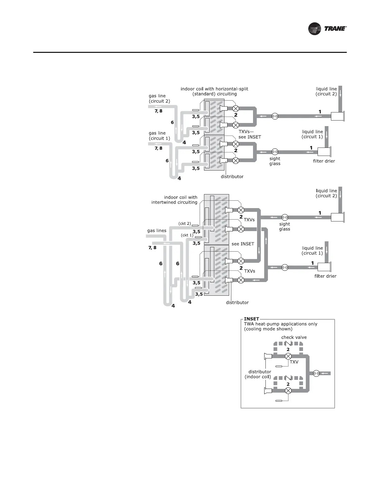
Figure 13. Indoor coil with four distributors (dual-circuit TTA/TWA units)
1 Pitch the liquid line 1 inch per 10 feet (1 cm per
3 m) so that the liquid refrigerant drains toward
the indoor coil. Use the liquid-line size
recommended in Table 2, p. 20 or Table 3, p. 21.
2 Provide one expansion valve (TXV)
per distributor.
TWA heat pumps only: Provide one check
valve for each expansion valve (see inset).
3 Pitch the gas line leaving the coil so that it
slopes away from the coil by 1 inch per 10 feet
(1 cm per 3 m).
4 Arrange the gas line so that suction gas leaving
the coil flows downward, past the lowest gas-
header outlet, before turning upward. Use a
double-elbow configuration on all lower branch
circuits to isolate the TXV bulb from suction-
header conditions. See “Gas Line: Routing,” p. 7
5 For all coil branch circuits in the gas line, use a
tube diameter that is one size smaller than the
gas-line size recommended in Ta bl e 2 or Tab l e 3.
6 For vertical risers, use the tube diameter
recommended in Ta ble 2 or Ta ble 3 . Ensure that
the top of the riser is at least 1 foot (30 cm)
above the lowest point.
7 Pitch the gas line by 1 inch per 10 feet (1 cm per
3m) toward the indoor coil.
8 Insulate the gas line.
 Loading...