32 18-CD19D8-18
Installer’s Guide
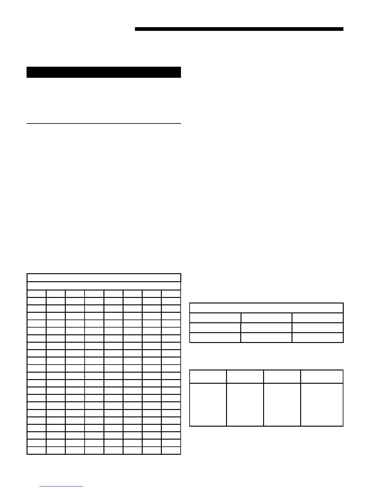
GAS FLOW IN CUBIC FEET PER HOUR
2 CUBIC FOOT DIAL
SEC. FLOW SEC. FLOW SEC. FLOW SEC. FLOW
8 900 29 248 50 144 82 88
9 800 30 240 51 141 84 86
10 720 31 232 52 138 86 84
11 655 32 225 53 136 88 82
12 600 33 218 54 133 90 80
13 555 34 212 55 131 92 78
14 514 35 206 56 129 94 76
15 480 36 200 57 126 96 75
16 450 37 195 58 124 98 73
17 424 38 189 59 122 100 72
18 400 39 185 60 120 104 69
19 379 40 180 62 116 108 67
20 360 41 176 64 112 112 64
21 343 42 172 66 109 116 62
22 327 43 167 68 106 120 60
23 313 44 164 70 103 124 58
24 300 45 160 72 100 128 56
25 288 46 157 74 97 132 54
26 277 47 153 76 95 136 53
27 267 48 150 78 92 140 51
28 257 49 147 80 90 144 50
TABLE 15
FINAL MANIFOLD PRESSURE SETTINGS (inches w.c.)
FUEL 2nd Stage Max. 1st Stage Max.
NATURAL GAS 3.5" W.C. 1.7" W.C.
LP GAS 10.5" W.C. 6.0" W.C.
TABLE 16
TABLE 17
PART NUMBERS FOR REPLACEMENT ORIFICES
DRILL
SIZE
PART
NUMBER
DRILL
SIZE
PART
NUMBER
44
45
46
47
48
49
50
ORF00501
ORF00644
ORF00909
ORF00910
ORF01099
ORF00503
ORF00493
54
55
56
57
58
59
ORF00555
ORF00693
ORF00907
ORF00908
ORF01338
ORF01339
6. Multiply the final figure by the heating value of the gas
obtained from the utility company and compare to the
nameplate rating. This must not exceed the name-
plate rating.
5. Adjust 1st stage gas heat by removing the low (LO)
adjustment regulator cover screw.
a. To increase outlet pressure, turn the regulator adjust
screw clockwise.
b. To decrease outlet pressure, turn the regulator adjust
screw counterclockwise.
c. Adjust regulator until pressure shown on manometer
matches the pressure specified in Table 16.
1. The input of no more than nameplate rating and no
less than 93% of the nameplate rating, unless the unit
is derated for high altitude.
d. Replace and tighten the regulator cover screw securely.
6. Adjust 2nd stage gas heat by removing the high (HI)
adjustment regulator cover screw.
a. To increase outlet pressure, turn the regulator adjust
screw clockwise.
b. To decrease outlet pressure, turn the regulator adjust
screw counterclockwise.
c. Adjust regulator until pressure shown on manometer
matches the pressure specified in Table 16.
1. The input of no more than nameplate rating and no
less than 93% of the nameplate rating, unless the unit
is derated for high altitude.
d. Replace and tighten the regulator cover screw securely.
7. Cycle the valve several times to verify regulator setting.
a. Repeat steps 5-7 if needed.
8. Turn off all electrical power to the system.
9. Remove the manometer and flexible tubing and tighten
the pressure tap screw.
10. Using a leak detection solution or soap suds, check for
leaks at the pressure outlet boss and pressure tap test
screw.
11. Turn on system power and check operation of the unit.
WARNING
!
HAZARD OF EXPLOSION
REPLACE AND/ OR TIGHTEN ALL PLUGS REMOVED OR
LOOSENED WHEN ADJUSTING GAS PRESSURE. LEAK
CHECK THE FITTINGS BEFORE PLACING THE FURNACE
INTO REGULAR SERVICE.
FAILURE TO FOLLOW THIS WARNING COULD RESULT IN
FIRE, EXPLOSION, PROPERTY DAMAGE, OR DEATH.
Gas Valve Adjustment
Changes can be made by adjusting the manifold pressure
(See Table 16), or changing orifices (orifice change may
not always be required). To adjust the manifold pres-
sure:
1. Turn off all electrical power to the system.
2. Attach a manifold pressure gauge with flexible tubing to
the outlet pressure boss marked “OUT P” on White-
Rodgers gas valve model 36G or 36J. See Figure 53 for
White-Rodgers gas valve model 36J. See Figure 54 for
White-Rodgers gas valve model 36G.
3. Loosen (Do Not remove) the pressure tap test set screw
one turn with 3/32" hex wrench.
a. The pressure tap adjustment kit (KIT07611)
contains a 3/32" hex wrence, a 5/16" hose and a
connector and can be ordered through Global Parts.
4. Turn on system power and energize valve.
 Loading...