EasyManua.ls Logo

Trane TZON1050 User Manual

Trane TZON1050
32 pages
To Next Page IconTo Next Page
Page #1 background imageLoading...
Page #1 background image
TZON1050 Installation Guide
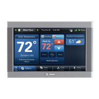
ComfortLink™ II XL1050
Communicating Connected Control
ALL phases of this installation must comply with NATIONAL, STATE AND LOCAL CODES
IMPORTANT — This Document is customer property and is to remain with this unit.
These instructions do not cover all variations in systems or provide for every possible contingency to be met in connection with
the installation. Should further information be desired or should particular problems arise which are not covered sufficiently
for the purchaser’s purposes, the matter should be referred to your installing dealer or local distributor.
18-HD80D1-6E-EN
Questions and Answers:

Trane TZON1050 Specifications

General IconGeneral
Power Source24V AC
DisplayColor Touchscreen
ConnectivityWired
User InterfaceTouchscreen
Energy ManagementYes
ProgrammableYes
Humidity ControlYes
Indoor Temperature SensorYes
Communication ProtocolProprietary
Remote AccessYes

Summary

Safety

Wiring and Electrical Safety Precautions

Guidelines for proper wiring practices and warnings about live electrical components during installation.

Installation

Location

Guidance on selecting an optimal installation location for the 1050 Control.

Wiring

Procedures for connecting control wires and sealing the wall opening.

Field Wiring Connection Diagrams

System Setup

Installer Setup Screens

Overview of configuring parameters via Installer Setup Screens.

Group 1 - Standard Settings

Configure basic equipment components and system operation settings.

Group 2 - Zoning Settings

Settings for enabling and configuring zoning capabilities.

Group 2* - Equipment Settings

Configure equipment settings like cycles per hour for various stages.

Group 5* - Comfort Settings

Adjust comfort-related settings like dehumidification and aggressive recovery.

Group 6* - Airflow Settings

Configure blower on/off delays and compressor low stage airflow percentages.

Group 7* - Lockout Settings

Configure lockout settings based on outdoor temperature for various operations.

Indoor Sensor Setup

Procedure for assigning temperature sensors to specific zones.

Basic Operation – Non-Zoned

Stage Thresholds

Defines load value thresholds for enabling additional equipment stages.

Advanced Operation

Lockouts

Configure lockout settings based on outdoor temperature for various operations.

Stage Inhibits

Limits equipment staging by calculating recovery rate over a 10-minute period.

Diagnostic Tools

Test Modes

Tools for testing system components and operation.

Non-Variable Speed

Test modes for non-variable speed blower and compressor operations.

Variable Speed

Test modes for charging and checkout of variable speed systems.

Diagnostics

Accessing system alerts, summary tables, and history for diagnostics.

Alerts

View and categorize active and historical system alerts.

Troubleshooting

Related product manuals