2
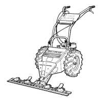
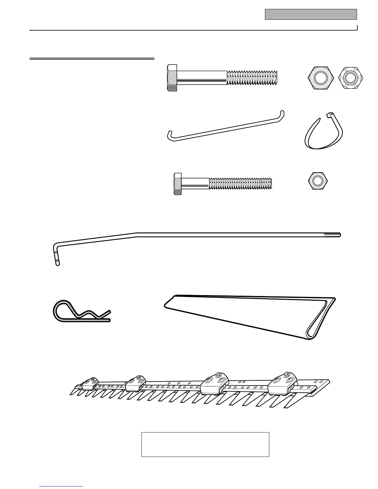
Ref. Description Qty.
Right Handlebar (shipped connected to
unit by wiring)...............................................1
Left Handlebar (shipped connected to
unit by wiring)...............................................1
1 Hex Head Capscrew, 5/16"–18 x 2-1/4" ........2
2 Locknut, 5/16"–18.......................................10
3 Handlebar Bridge ..........................................1
4 Cable Ties (total of six - two already
installed on unit)...........................................4
5 Hex Head Capscrew, 1/4"–20 x 2" .................1
6 Locknut, 1/4".................................................1
7 Control Rod ..................................................2
8 Hair Pin ..................................................2
9 Plastic Blade Guard (on blade)......................1
10 Cutter Bar......................................................1
HARDWARE IS APPROXIMATE SIZE SHOWN
Large parts (with
*) shown reduced
1
4*
8
7*
9*
10*
5
6
3*
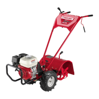
Ref. Description Qty.
-- Right Handlebar (shipped connected to
unit by wiring)..............................................1
-- Left Handlebar (shipped connected to
unit by wiring)..............................................1
1 Hex Head Capscrew, 5/16"–18 x 2-1/4" ...........2
2 Toplock Nuts, 5/16"–18 (to mount
handlebars)..................................................2
2a Nylock Nuts, 5/16"–18 .....................................8
3 Handlebar Bridge .............................................1
4 Cable Ties (total of six - two already
installed on unit) ..........................................4
5 Hex Head Capscrew, 1/4"–20 x 2" ....................1
6 Locknut, 1/4"....................................................1
7 Control Rod (attached to handlebars) ..............2
8 Hair Pin Clip.....................................................2
9 Plastic Blade Guard (on Cutter Bar Assembly).1
10 Cutter Bar.........................................................1
5
8
1
6
2
2a
3*
7*
NOTE: Control rods are attached to one handlebar with a wire tie (see Fig. 2-1). Cut
wire tie and remove rods before starting assembly steps.
9*
10*
4*
HARDWARE IS SHOWN APPROXIMATE SIZE
(Large parts [with *] shown reduced size)
 Loading...