TFP1090
Page 4 of 26
Technical
Data
Approvals
Model DPV-1 Dry Pipe Valves with
or without the TYCO Model ACC-1
Dry Pipe Valve Accelerator are FM,
LPCB, VdS, and CE Approved with
European Conformity Valve Trim. See
Figures 7 to 18.
For more information on Agency
Approvals, contact Johnson Controls
at the following office:
Kopersteden 1
7547 TJ Enschede
The Netherlands
Tel: +31-(0)53-428-4444
Fax: +31-(0)53-428-3377
Dry Pipe Valve
The DN65, DN80, DN100, and DN150
Model DPV-1 Dry Pipe Valves are
for vertical installations (flow going
up), and they are rated for use at a
maximum service pressure of 16 bar.
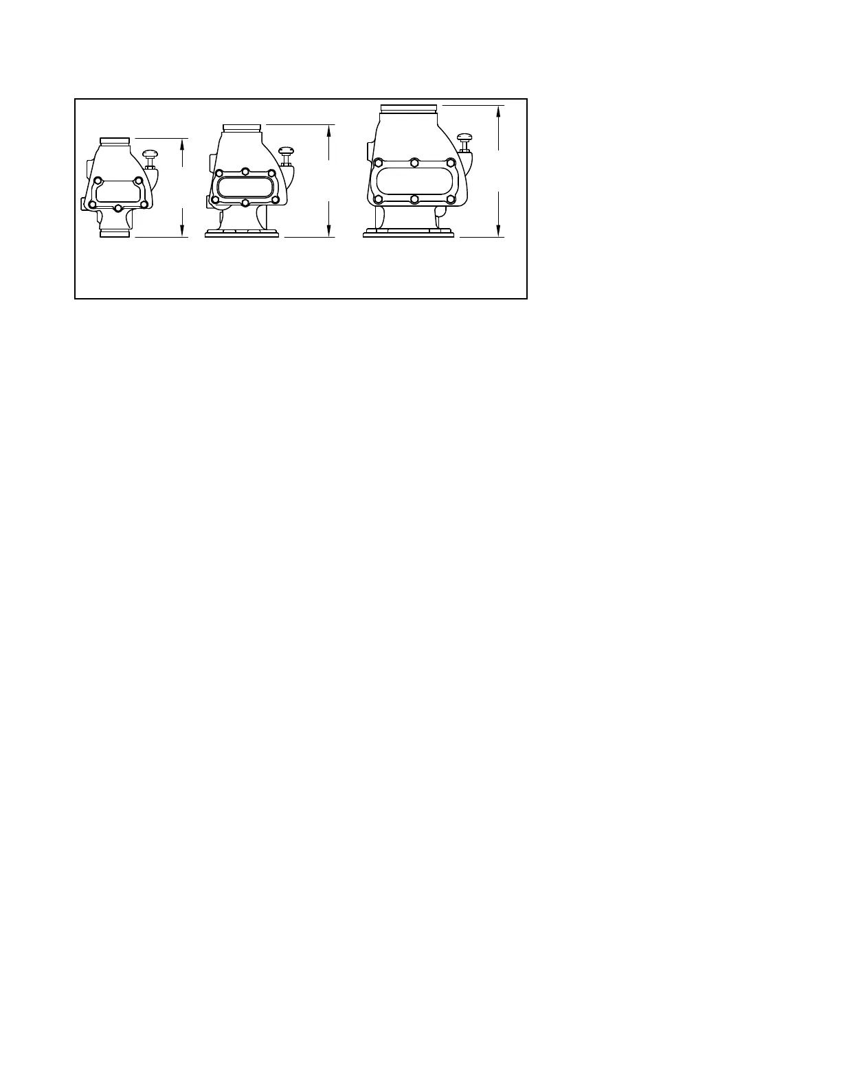
The nominal pressure loss versus flow
is shown in Graph A, and the valve
take-out dimensions are shown in
Figure 2.
Flange connections are drilled per ISO
2084 (PN10/16) or ANSI B16.1 (Class
125). The grooved outlet connections,
as applicable, are cut in accordance
with standard groove specifications
for steel pipe. They are suitable for use
with grooved end pipe couplings that
are listed or approved for fire protec-
tion system service.
Threaded port connections per ISO
7-1 readily accept trim arrangements
described in Figures 7 through 18.
Components of Model DPV-1 Valve
assemblies are shown in Figure 1A
for the DN65, DN80, and DN100
valves and in Figure 1B for the DN150
valve. The Body and Handhole Cover
are ductile iron. The Handhole Cover
Gasket is neoprene, and the Clapper
Facing is EPDM. The Air/Water Seat
Ring is brass, the Clapper is copper,
and both the Clapper Retaining Plate
and Latch are bronze. The Hinge Pin is
aluminum bronze, and the fasteners for
the Handhole Cover are carbon steel.
Valve Trim
Valve trim arrangements are shown in
Figures 7 through 18. See Table A. The
Valve Trim forms a part of the labora-
tory approval of the Model DPV-1 Dry
Pipe Valve and is necessary for the
proper operation of the Model DPV-1
Dry Pipe Valve. Each package of trim
includes the following items:
• Water Supply Pressure Gauge
• System Air Pressure Gauge
• Main Drain Valve
• Low Body Drain Valve
• Alarm Test Valve
• Automatic Drain Valve
• Provision For An Optional Accelerator
Air Supply
Table B provides system air pressure
requirements as a function of the water
supply pressure. The air (or nitrogen)
pressure in the sprinkler system is rec-
ommended to be automatically main-
tained by using one of the following
pressure maintenance devices, as
appropriate:
• Model AMD-1 Air Maintenance
Device (pressure reducing type).
Refer to Technical Data Sheet
TFP1221.
• Model AMD-2 Air Maintenance
Device (compressor control type).
Refer to Technical Data Sheet
TFP1231.
• Model AMD-3 Nitrogen Mainte-
nance Device (high pressure reduc-
ing type). Refer to Technical Data
Sheet TFP1241.
Quick Opening Device
As an option, the Model DPV-1 Dry
Pipe Valve may be acquired with the
Model ACC-1 Dry Pipe Valve Acceler-
ator. See Figure 4. The Model ACC-1
Dry Pipe Valve Accelerator is used to
reduce the time to valve actuation fol-
lowing the operation of one or more
automatic sprinklers.
Operating
Principles
Dry Pipe Valve Operation
The TYCO Model DPV-1 Dry Pipe Valve
is a differential type valve that utilizes a
substantially lower system (air or nitro-
gen) pressure than the supply (water)
pressure, to maintain the set position
shown in Figure 3A. The differential
nature of the Model DPV-1 Dry Pipe
Valve is based on the area difference
between the air seat and the water
seat in combination with the ratio of the
radial difference from the Hinge Pin to
the center of the Water Seat and the
Hinge Pin to the center of the Air Seat.
The difference is such that the Model
DPV-1 has a nominal trip ratio of 5.5:1
(water to air).
Table B establishes the minimum
required system air pressure that
includes a safety factor to help prevent
false operations that occur due to water
supply fluctuations.
The Intermediate Chamber of the Model
DPV-1 Dry Pipe Valve is formed by the
area between the Air Seat and Water
Seat as shown in Figure 3B. The Inter-
mediate Chamber normally remains
at atmospheric pressure through the
Alarm Port connection and the valve
trim to the normally open Automatic
Drain Valve. See Figures 7 to 18. Having
the Intermediate Chamber, Figure 3B,
open to atmosphere is critical to the
Model DPV-1 Valve remaining set, oth-
erwise the full resulting pressure of
the system air pressure on top of the
Clapper Assembly cannot be realized.
For example, if the system air pres-
sure is 1,7 bar and there was 1,0 bar
pressure trapped in the Intermediate
Chamber, the resulting pressure across
the top of the Clapper would only be
0,7 bar. This pressure would be insuf-
ficient to hold the Clapper Assembly
closed against a water supply pres-
sure of 6,9 bar.
When one or more automatic sprinklers
operate in response to a fire, air pres-
sure within the system piping is relieved
through the open sprinklers. When the
air pressure is sufficiently reduced,
the water pressure overcomes the dif-
ferential holding the Clapper Assem-
bly closed and the Clapper Assembly
swings clear of the water seat, as
shown in Figure 3C. This action permits
water flow into the system piping and
subsequently to be discharged from
any open sprinklers. Also, with the
Clapper Assembly open, the interme-
diate chamber is pressurized and water
DN100 DN150DN65, DN80
FxF, FxG,
406 mm
or GxG
FxG 348 mm
FxF 346 mm
GxG 349 mm
GxG
311 mm
ONLY
FIGURE 2
MODEL DPV-1 DRY PIPE VALVE
TAKE-OUT DIMENSIONS

 Loading...