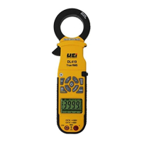
DL419
FUNCTIONS
• AC/DC Voltage
............................................
• AC/DC Current
............................................
• AC/DC MicroAmps
........................................
• Audible continuity ............................................
• Resistance ....................................................
• Diode test ....................................................
• Capacitance ..................................................
FEATURES
• True RMS
• LRA Inrush current measurement
• Data hold mode
HOLD
• MIN/MAX (All ranges except Capacitance)
................
Min/Max
• Rel/DC A Zero mode
....................................
Rel/Zero
• Back-lit display ................................................
• Non-contact voltage detect ....................................NCV
• Magnetic mount
• Autoranging measurements with manual ranging capability
• Bar Graph
a. The bar graph shows an approximate analog representation of a
measurement.
b. The bar graph responds much faster than the digital display.
c. The scale of the bar graph is zero to the maximum reading of
the selected range.
• Auto-Power-Off: After 30 minutes of non-use
• Low battery: is displayed if battery voltage drops below
operating voltage.
GENERAL SPECIFICATIONS
• Altitude: Operating - up to 2000m (6,561 ft.)
Storage - 10,000m (32,808 ft.)
• Humidity: 80% max
• Operating Temperature: 32°F to 104°F (0°C to 40°C) at < 75% R.H
• Storage Temperature: -4°F to 140°F (-20°C to 60°C) at < 80% R.H
• Relative humidity: 0% to 80% at 32°F to 95°F (0°C to 35°C),
0% to 70% at 32°F to 131°F (0°C to 55°C)
• Temperature Coefficient: Nominal 0.1 x (Specified accuracy) / °C
(<18°C or >28°C ; <64°F or >82°F)
• Pollution degree: 2
• Display: 3-3/4 digits 4000 counts single LCD display with 20 segments
bar graph
• Refresh Rate: 3 times/sec
• Overrange: "OL" is displayed
• Polarity: Automatic(no indication for positive polarity) ; Minus(-) sign
for negative polarity
• Dimensions: 10.6" x2.5" x 1.5"
• Weight: 16.8oz.
• Calibration: Accurate for one year
• CAT Rating: CAT IV 600V, CAT III 1000V
• Certifications: ETL & C-ETL Listed IEC61010-2-032
• Battery type: 2 x 1.5V AAA or LR03
• Silicon Test Lead: IEC61010-2-031
• Accuracy: ± (% of reading + # of least significant digits)
WARNINGS
To ensure safe operation and service of the tester, follow these instructions.
Failure to observe these warnings can result in severe injury or death.
• Before each use, verify meter operation by measuring a known voltage or
current.
• Never use the meter on a circuit with voltages that exceed the category
based rating of this meter.
• Do not use the meter during electrical storms, or in wet weather.
• Do not use the meter or test leads if they appear to be damaged.
• Ensure meter leads are fully seated, and keep fingers away from the metal
probe contacts when making measurements.
• Do not open the meter to replace batteries while the probes are connected.
• Use caution when working with voltages above 60V DC, or 25V AC RMS.
Such voltages pose a shock hazard.
• To avoid false readings that can lead to electrical shock, replace batteries
if a low battery indicator appears.
• Unless measuring voltage or current, shut off and lock out power before
measuring resistance or capacitance.
• Always adhere to local and national safety codes. Use Personal Protective
Equipment (PPE) to prevent shock and arc blast injury.
SYMBOLS USED ON LCD
~
AC Measurement DC Measurement
Negative DC Value
AT
Auto Range Active
O.L.
Overload: Range Exceeded
Apo
Auto Power-Off Active
Low Battery
HOLD
Hold Active
MIN
Minimum Reading
M
AX
Maximum Reading
Relative / Zero Mode
A
Current in Amps
V
Voltage Measurement Diode Test
Ω
Resistance in Ohms
k
Kilo ( x 10
3
)
µA
MicroAmps
M
Mega ( x 10
6
)
m
Milli ( x 10
-3
)
nF/µF
Nanofarad/Microfarad
INTERNATIONAL SYMBOLS
~
AC Alternating Current Warning or Caution
DC Direct Current Dangerous levels
DC/AC Voltage or Current Double Insulated Class II
Ground
Safe for disconnect
from live conductors
AC Source
True RMS Digital Clamp-On
Multimeter
PLEASE
RECYCLE
10093 01/15
WARRANTY
The DL419 is warranted to be free from defects in materials and workmanship
for a period of two year from the date of purchase. If within the warranty
period your instrument should become inoperative from such defects, the unit
will be repaired or replaced at UEi’s option. This warranty covers normal use
and does not cover damage which occurs in shipment or failure which results
from alteration, tampering, accident, misuse, abuse, neglect or improper
maintenance. Batteries and consequential damage resulting from failed
batteries are not covered by warranty.
Any implied warranties, including but not limited to implied warranties of
merchantability and fitness for a particular purpose, are limited to the express
warranty. UEi shall not be liable for loss of use of the instrument or other
incidental or consequential damages, expenses, or economic loss, or for any
claim or claims for such damage, expenses or economic loss.
A purchase receipt or other proof of original purchase date will be required
before warranty repairs will be rendered. Instruments out of warranty will be
repaired (when repairable) for a service charge.
BATTERY REPLACEMENT
• When indicator is displayed on the LCD, batteries must be replaced.
• Remove the back screw and replace 2 x AAA batteries.
CLEANING
Turn instrument off and disconnect test leads. Clean the instrument by using
a damp cloth. Do not use abrasive cleaners or solvents.
STORAGE
Remove the batteries when instrument is not in use for a prolonged period
of time. Do not expose to high temperatures or humidity. After a period
of storage in extreme conditions exceeding the limits mentioned in the
Specifications section, allow the instrument to return to normal operating
conditions before using it.
DISPOSAL / RECYCLE
Caution: This symbol indicates that equipment and its
accessories shall be subject to a separate collection and correct
disposal.
Copyright © 2015 UEi. All Rights Reserved
CAT III 1000V
CAT IV 600V
DL419
True RMS
600V 1000A
CAT IV
NCV
MAX/
MIN
LRA
Inrush
Zero
DC/
Rel
RANGE
INRUSH
V
O
L
T
A
G
E
D
E
T
E
C
T
O
R
μ
A
A
V
MFD
INSTRUCTION MANUAL
ENGLISH
NAVIGATION
• Press briefly to turn the meter on
• Press and hold “HOLD” while turning on
to disable auto power off.
• Press and hold to turn the meter off
• Default is AC Volts
The new user interface allows direct access from any mode.
• Press to select DC µA measurement mode.
• Press a second time for AC µA.
• Press to select AC Amps.
• Press a second time for DC Amps.
MFD
• Press to select continuity.
• Press a second time for resistance.
• Press a third time for capacitance and a fourth time for diode.
V
• Press to select AC Volts.
• Press again to select DC Volts.
NCV
• Non-Contact Voltage Detection key is used to detect power with a
sensor located at the tip of the clamp head and indicates positive
response with an audible alarm and visual LED indicator light just
above the “NCV” button.
• Do not use non-contact voltage detector to determine if there
is current in the wire. Detection operation could be affected by
socket design, insulation thickness, type and other factors.
• Voltage indicator light may also light when voltage is present on
the meter’s input jack or from external interference sources such
as motors, flashlights etc.
MAX/
MIN
• Press to enter Max / Min mode; the largest and smallest values
will be saved while in this mode.
• Press repeatedly to alternate between the maximum and
minimum readings.
• Press for 2 seconds to return to live reading and clear the stored
maximum and minimum values.
Note: Select range prior to selecting Min/Max to capture large
values
RANGE
• Press repeatedly to cycle through manual ranges.
• Press for 2 seconds to return to auto ranging mode.
• AT is displayed on LCD only during auto ranging mode.
Note: Select range prior to Min/Max for best results.
x1x1
Zero
DC/
Rel
• Press to zero any offset in Volts AC/DC, DC µA, Amps AC/DC.
◊ Used to monitor change from the present displayed value
• Required during DC Amp measurement to establish a zero level
DO NOT use Zero DC/Rel mode at voltages greater than
1000V.
HOLD
• Press to hold the reading on the display. Press again to return to
live reading.
• Press and hold "work light" key for 2 seconds to turn on. Press and
hold again to turn off.