UT204+UT203+
40.00A
400.0A
60.00A
600.0A
0.01 A
0.1 A
±(2%+5)
UT204+UT203+
40.00A
400.0A
60.00A
600.0A
0.01 A
0.1 A
±(2%+5)
UT204+UT203+
400.0mV
4.000V
40.00V
400.0V
600V
600.0mV
6.000V
60.00V
600.0V
0.1mV
0.001V
0.01V
0.1V
1V
±( . +0 7% 3)
±( . +0 5% 2)
UT204+UT203+
4.000V
40.00V
400.0V
600V
6.000V
60.00V
600.0V
0.001V
0.01V
0.1V
1V
0.01Hz~0.01kHz
±( . +1 0% 5)
±( . +0 8% 5)
±( . %+ )0 5 2Voltage Frequency
10Hz 60KHz~
0 1. Ω
0 001V.
400.0Ω/600.0Ω
4.000V/6.000V
UT204+UT203+
400.0Ω
4.000kΩ
40.00kΩ
400.0kΩ
4.000MΩ
40.00MΩ
600.0Ω
6.000kΩ
60.00kΩ
600.0kΩ
6.000MΩ
60.00MΩ
0 1. Ω
0 001K. Ω
0 01K. Ω
0 1K. Ω
0 001M. Ω
0 01M. Ω
±( . +1 0% 2)
±( . +0 8% 2)
±( . %+ )2 5 5
UT204+UT203+
40.00nF
400.0nF
4.000uF
40.00uF
400.0uF
4.000mF
40.00mF
60.00nF
600.0nF
6.000uF
60.00uF
600.0uF
6.000mF
60.00mF
0.01nF
0.1nF
0.001μF
0.01μF
0.1μF
0.001mF
0.01mF
±( %+ )4 5
± %10
10Hz~10MHz 0.01Hz~0.01MHz
±(0.1%+4)
0.1%~99% 0.1%
±(3%+5)
10.9 NCV
NCV
EFLo
EFHI
LIVE
-40℃~40℃
40℃~500℃
500℃~1000℃
-40℉~104℉
104℉~932℉
932℉~1832℉
±4℃
±(1.5%+5)
±(2.0%+5)
±6℉
±(2.0%+6)
±(2.5%+4)
1℃
1℉
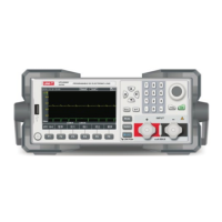
9.5 NCV AC Electric Field Sensing and Live/Neutral Wire
Measurement (Picture 6a)
9.5.1 AC Electric Field Sensing
The electric field sensing sensitivity is divided into two levels
(“EFHI” and “EFLo”). The meter defaults to “EFHI”. Users can select
different sensitivity levels according to the intensity of the measured
electric field. Select "EFHI" of NCV when electric field is around 220V
AC 50Hz/60Hz. Bring the NCV sensing end close to a charged electric
field (socket, insulated wire, etc.). The LCD will display the segment
"-" with beeps and red LED flashing. As the intensity of the measured
electric field increases, the more segments (----) display , the higher
frequency of buzzer beeps and LED flashes. Select “EFLo” when the
electric field is around 110V AC 50Hz/60Hz.
Caution:
Use the NCV sensing end to approach measured electric field,
otherwise the measurement sensitivity will be affected. When the
measured electric field voltage is over 100V AC, observe whether the
conductor is insulated to avoid personal injury.
9.5.2 Live/Neutral Wire Measurement (only UT204+) (Picture 6b)
a. Select the LIVE function scale.
b. Insert the red test lead into the “ ” jack, make the black
suspended, and use the red test lead to touch the socket test lead
to distinguish the live/neutral wire. or bare wire
c. When the neutral wire or uncharged object is detected, the "----" is
displayed.
d. When the >60V AC "live wire" is detected, the LCD will display
accompanied by audio/visual indication. "LIVE"
Caution:
When using this function, in order to avoid the COM input interference,
which will affect the electric field and the accuracy, please pull the
black test lead out of the COM input.
Do keep your hand away from the meter casing. The accuracy may
be unstable under the dense high-voltage. In this case, it should
be judged by LCD and sound frequency together.
9.6 Others
Auto power off: The meter will automatically power off to save power
if there is no operation for 15 min. You can wake it up by pressing
any button or restart it after turning the switch to OFF.
Press and hold the SELECT button in off state and then turn on the
meter again to disable the auto power off function. Restart the meter
after shut it down to resume this function.
Buzzer: When any button is pressed or the function switch is turned,
if it is valid, the buzzer will make one beep (about 0.25s). The buzzer
will also beep intermittently to indicate the over range during the
voltage or current measurement.
Low battery detection: The battery voltage will be automatically
detected as long as the meter is on. If it is lower than 2.6V, the LCD
will display the “ ” symbol.
Low battery shutdown function: When the battery voltage is lower
than 2.5V, the LCD displays the “ ” symbol, the “Lo.bt” interface
appears and lasts for about 10s, the buzzer makes consecutive
beeps 3 times, and then the meter automatically shuts down (no
is displayed).interface
10. Technical Specifications
Accuracy: ± (%reading + counts), the calibration period is 1 year.
Ambient temperature and humidity: 23°C±5°C; ≤80%RH.
Temperature coefficient: the accuracy assured temperature condition
is 18°C-28°C, the range of ambient temperature fluctuation is stable
within ±1°C. When the temperature is less than 18°C or over 28°C,
the additional temperature coefficient error is 0.1 x (specified
accuracy)/°C.
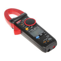
10.1 Current Measurement
AC Current
Range
Resolution
Accuracy
DC Current
Caution:
Accuracy guarantee range: 5%~100% of range
When the measured current reaches the warning value, there
will be an alarm sound (UT203+: 410A, UT204+: 610A)
With DC current DCA mode, LCD may display non-zero value
in open circuit state, users can press "REL" button to clear display
to zero before each measurement.
10.2 Voltage Measurement
DC Voltage
Range
Resolution
Accuracy
AC Voltage/Voltage Frequency
Range
Resolution
Accuracy
Caution:
UT203+: short press "SELECT” in AC voltage/Hz scale to enter the Hz
function;
UT204+: long press "SELECT" to enter/exit the Hz function, the input
range over 5V.
The input impedance is about 10MΩ
Current/voltage frequency response: 45Hz ~ 400Hz, displays true RMS
value
Accuracy guarantee range: 1%~100%
AC crest factor of non-sinusoidal wave can reach 3.0 at 4000 counts
while can only reach 1.8 at 6000 counts, the additional error should be
added for the corresponding crest factor as follows:
A. Add 3% when the peak factor is 1 ~ 2
B. Add 5% when the peak factor is 2 ~ 2.5
C. Add 7% when the peak factor is 2.5 ~ 3
10.3 Continuity/Diode Measurement
Function
Range
Resolution
Accuracy
≤10Ω: Consecutive beeps
≥31Ω: No beep
The median: uncertain
The open circuit voltage is
about 4V
For the silicon PN junction
diode, the voltage value is
generally about 0.5~0.8V.
10.4 Resistance Measurement
Range
Resolution
Accuracy
Caution:
Measured resistance value = displayed value – resistance value
of short circuited test leads
Open circuit voltage is about 1V
Overload protection: 600Vrms
10.5 Capacitance Measurement
Range
Resolution
Accuracy
Caution:
Measured value = displayed value - open circuit value of the test leads
(For capacitance ≤100nF, “REL” mode is recommended, open circuit
has residual reading). The guaranteed accuracy is 1%~100%.
Overload protection: 600Vrms
10.6 Frequency Measurement
Range
Range
Resolution
Resolution
Accuracy
Accuracy
10.7 Duty Ratio Measurement
Caution:
Measurement sensitivity:
≤100kHz: 200mVrms≤ input range≤30Vrms;
>100kHz~1MHz: 600mVrms≤ input range≤30Vrms;
>1MHz~10MHz: 1Vrms≤ input range≤30Vrms.
Duty ratio is only applicable to ≤10kHz square wave measurement
with a range of 1Vp-p:
If frequency≤1kHz, duty cycle will be 10.0%-95.0%;
If frequency>1kHz, duty cycle will be 30.0%-70.0%.
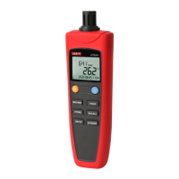
10.8 Temperature Measurement (UT204+ only)
Range
Resolution
Accuracy
Caution:
The meter displays "OL" after startup, it is only suitable for K-type
thermocouple (Nickel-Chromium ~ Nickel-Silicon temperature
sensor) and temperature measurements below 1000°C/1832°F.
The formula for Celsius to Fahrenheit is °F =1.8°C + 32.
Range
Electric field
sensing
sensitivity level
Accuracy
The electric field sensing sensitivity
is divided into two levels (“EFHI” &
“EFLo”). The meter defaults to “EFHI”.
a) AC voltage above 24V±6V can be
sensed. "EFLo" mode is recommended
when the power frequency voltage is
110V.
b) "EFHI" can be set in 220V condition.
AC voltage above 74V±12V can be
sensed with getting close to wires,
and identify whether the main socket
is charged or to judge the live/neutral
wire of socket according to the intensity
of sensing.
Note: Test results may be affected by
different socket designs or wire I
nsulation thickness.
10.10 LIVE Function (UT204+ only)
Range
Live wire measurement
Accuracy
1) Display "- - - -" and "AC"
symbol before startup
2) Display "- - - -" when test
neutral wire.
3) Display "LIVE" and symbol
when test live wire, and change
sound and LED flashing
frequency according to the live
wire voltage intensity.
Triggered
voltage≥AC 60V
(50Hz/60Hz)
11. Maintenance
Warning: Before opening the rear cover of meter , remove test
leads to avoid electric shock.
11.1 General Maintenance
Clean the meter casing with a soft cloth and mild detergent. Do
not use abrasives or solvents!
Do not use the tester or test leads if they appear to have any
abnormality.
The maintenance and service must be implemented by qualified
professionals or designated departments.
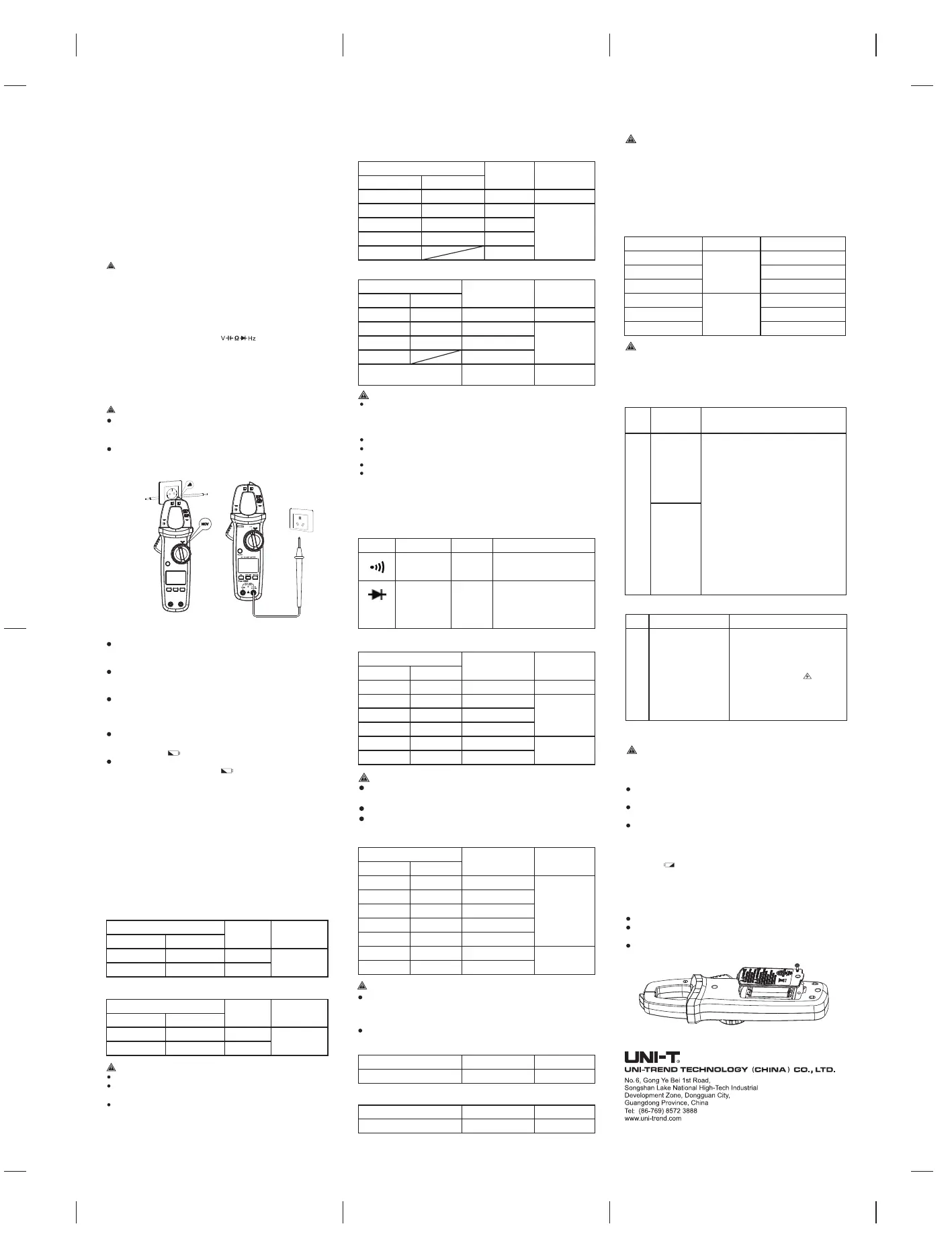
11.2 Battery Replacement (Picture 7)
When the “ ” symbol appears on the LCD, please replace the
batteries in time to ensure measurement accuracy. Batteries
specification:
2 standard AAA 1.5V batteries.
Operation
Turn off the meter and remove the test leads from the input terminals.
Unscrew the screw of the battery compartment, remove the battery
cover, and take out the used batteries as shown.
Replace the 2 standard AAA batteries according to the polarity
indication.
Range
Resolution
Accuracy
Picture 7
Red
Picture 6b
Picture 6a

 Loading...