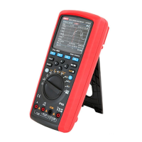
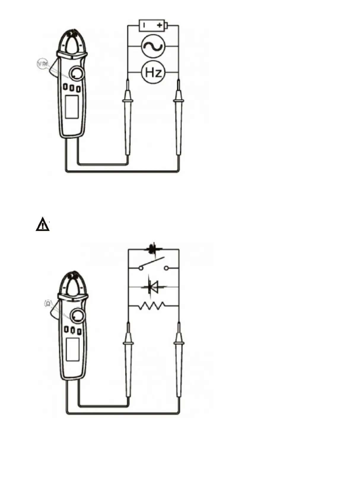
2. Measuring of Resistance/Circuit on-off/ Diode /Capacitance
• Select corresponding functions.
• Insert red probe into red jack (positive end), and insert black probe into black jack (COM end).
• Connect the probe in parallel to the measured part (Figure 3).
• Read the measured value from LCD screen. Do not input voltage of higher than DC 60V or AC 30V ,
when measuring the range of resistance/capacitance/ diode, in order to avoid personal injury or damage
of instrument.
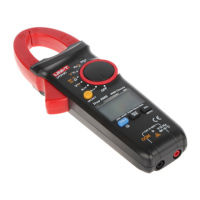
3. 3. Measuring of AC/DC Current (Figure 4)
1) AC current
• Select geometric center position of AC current tap position; make sure the left and right clamp heads are
completely closed, with no gap between them.
Read the measured data from LCD.
2) DC current
• Select DC current tap position.
 Loading...