English
GREAT BRITAIN • customer service tel: 0845 300 9799 e-mail: customerservice@clasohlson.co.uk internet: www.clasohlson.com/uk
Ver. 20140228
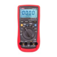
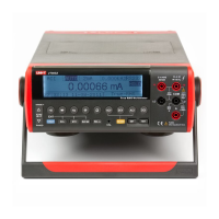
USB Multimeter
Art.no 36-4717 Model UT61D
Note: This is only a quick-start guide. For complete instructions
please refer to the accompanying CD.
Please read theentire instruction manual before use and save it for
future reference. Wereserve theright for any errors in text or images
and for making any necessary technical changes to this document.
Ifyou should have any questions concerning technical problems
please contact our Customer Services.
1. Safetyinstructions
• This meter is designed for indoor use.
• Do not use this meter if it or thetest leads appear to be
damaged, or if you suspect that themeter might not work
properly.
• Make sure that your fingers are behind thefinger guards when
using thetestleads.
• Make sure that thepower is turned off before working on
thepower circuit. Evenlow voltages can be dangerous!
• To avoid shocks you need to be careful when you work with
voltage higher then 60 V DC or 30 V AC RMS. Voltages higher
than this pose arisk of heavy electric shocks.
• Set theright measuring range using theselector before
starting to measure and do not change therange whilst taking
ameasurement.
• This meter is protected by fuses, but they will not protect
themeter from all kinds of misuse.
2. Functions
3. [ Range ]
• Pressonce to enter manual settings mode; thebuzzer
sounds once.
• Pressrepeatedly to advance through themeasuring ranges;
thebuzzer sounds.
• Holdin for two seconds to return to Autorange (automatic
measuring rangesetup).
4. [ Hold/Light ]
• Pressto save areading (data hold function), press once
more to delete thereading.
• Holdin for two seconds to turn on thedisplay backlight for
10 seconds.
5. Multifunction selector
8 different measuring functions and off switch.
6.
Testlead sockets
7.
Testlead sockets
8. [ REL ▲/RS 232 (USB) ]
• Pressonce to enter RELmode.
• Pressonce to exit RELmode.
• Holdin for two seconds to activate or deactivate theRS232/
USB function. Thesleep function is exited when theRS232/
USB function is activated and
disappears from
thedisplay.
9. [ Hz % ]
• Pressto measure frequency.
• Pressto select Duty Cyclevalue.
10. Alternative functions (blue button)
Press to select alternative functions for thesettings modes
inblue.
11.
Testlead sockets
12.
Testlead sockets
Display symbols
Thedata hold function is activated.
Thesleep mode is activated.
Indicates anegative reading.
Indicator for AC measurement.
Indicator for DC measurement.
TheAutorange is activated (meter automatically selects
therange with bestresolution).
Indicator for manual range mode (not on this model).
Thereading is too high for this measuring range.
Indicator for thediodetest.
Thecontinuity buzzer is activated.
Maximum and minimum reading.
Dataoutput in progress (USB/RS232).
Lowbattery warning – replace thebattery.
REL is activated, thestored value minus thepresent value
is displayed.
Resistance, Ω Ohm, kΩ (kiloohm), MΩ(megaohm).
Voltage, mV (millivolt), V (volt).
Current, μA (microampere), mA (milliampere),
A(ampere).
Capacitance; nF (nanofarad), μF (microfarad),
mF(millifarad).
Frequency, Hz (hertz), kHz (kilohertz),
MHz(megahertz).
3. Operation
• Warning: Consult a qualified electrician before using
theinstrument if you are at all unsure about its usage.
• Always ensure that thecorrect function and range is selected.
Ifin doubt about thecorrect range, start with thehighest and
work downwards.
• When measuring voltage always ensure that themeter
is switched to thecorrect function range and not set to
thecurrent, resistance or diode test range. Alwaysensure
that you use thecorrect test lead socket for thetype of
measurement to bemade.
• Make sure that theobject to be measured is not “live”, i.e.
conducting any current before connecting test leads in series
with it (such as when measuring current).
• Make sure that thetest leads are in good condition with no
damage to theinsulation.
4. Voltage measurement
Measuring DC voltage
6. Resistance measurement
1. LCD display
2. [ Max Min ]
• Pressto switch between max and min measured value.
• Holdin for two seconds to return to normal display.
1. Connect theblack test
lead to
and
thered test lead to
.
2. Setthefunction selector
to for DC voltage
measurement.
3. Ifyou wish to change
therange manually,
press [ Range ]
severaltimes.
4. Connect thetest leads
across thesource or
load to be measured.
5. DC and AC Current measurement
1. Connect theblack test
lead to and
thered test lead to
(for 0–600mA)
or to
(fortherange
600mA– 10A).
2. Setthefunction selector
to , or .
3. Themeter is preset to
measure DC, change
to AC using theblue
button(10).
4. Connect thetest leads
in series with thecurrent
source to be measured.
5. When measuring current
between 600 mA and
10A (without fuse) follow
themethod above but
connect thered test lead
to
instead.
1. Connect theblack test
lead to
and
thered test lead to
.
2. Setthefunction selector
to theresistance
measurement .
3. Connect thetest leads
across thecircuit to
betested.
7. Holdmode
1. Pressthe[ Hold/Light ] to save thepresent reading.
2. Thebuzzer sounds once and appears on thedisplay when
Hold is activated.
3. Thereading is deleted if you press thebutton onceagain.
8. Backlight
Hold in [ Hold/Light ] for two seconds to turn on thebacklight.
Thelight will turn off automatically after 10 seconds.
Measuring AC voltage
1. Connect theblack test
lead to and
thered test lead to
.
2. Setthefunction selector
to for AC voltage
measurement.
3. Ifyou wish to change
therange manually,
press [ Range ]
severaltimes.
4. Connect thetest leads
across thesource or
load to be measured.
1
3
4
5
7
2
6
8
9
10
11
12