P/N :110401104421X
** END **
This operating manual is subject to change without notice.
Figure 7
z When continuity testing has been completed,
disconnect the connection between the testing leads
and the circuit under test.
Measuring Capacitance
(See Figure 7)
The capacitance ranges are: 40.00nF, 400.0nF,4.000μF,
40.00μF, and 100.0μF. To measure capacitance,connect
the Meter as follows:
red black
1. Insert the red test lead into the HzVΩ terminal and
the black test lead into the COM terminal.
2. Set the rotary switch toΩ and press SELECT
button to select measurement mode. The existing
of the Meter built-in equalized capacitance will affect
the accuracy. To increase the accuracy of capacitance
measurement, press button before measuring to
reset the display to 0.
3. Connect the test leads across with the object being
measured.
The measured value shows on the display.
Note
z The LCD displays OL indicating the capacitor is short
-circuited or the capacitor value being tested is overload.
Figure 8
z For testing the capacitor with polarity, connect the
red test lead to anode & black test lead to cathode.
z It takes a longer time when testing a capacitor value
which is higher than 10μF range.
z When capacitance measurement has been completed,
disconnect the connection between the testing leads
and the circuit under test.
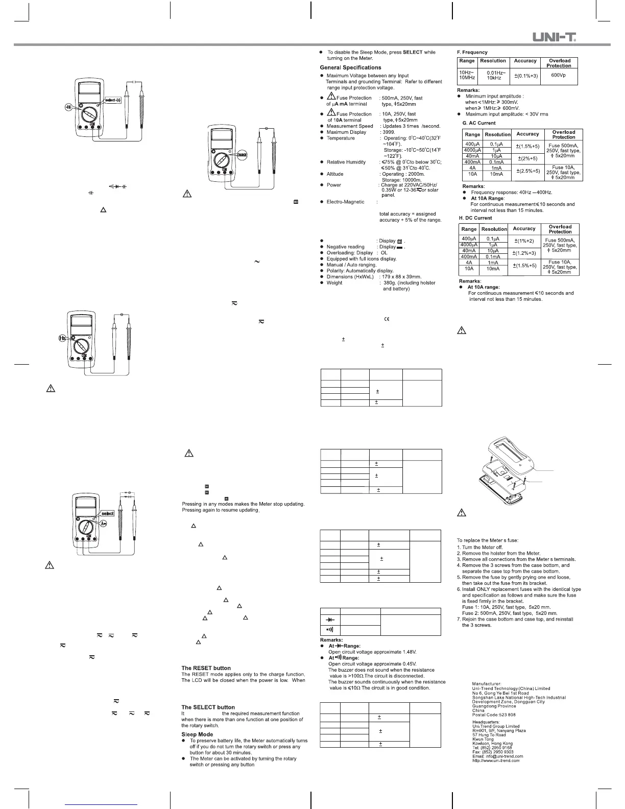
C.Measuring Frequency
(See Figure 8)
Warning
To avoid harm to you, please do not attempt to
input frequency voltage being tested higher than 30V.
red black
The measurement ranges are from 10Hz to 10MHz.
To measure frequency, connect the Meter as follows:
1. Insert the red test lead into the HzVΩ terminal and
the black test lead into the COM terminal.
2. Set the rotary switch to Hz.
3. Connect the test leads across with the object being
measured.
The measured value shows on the display.
Figure 8
black red
Note
z When Hz measurement has been completed,
disconnect the connection between the testing leads
and the circuit under test.
D.Measuring DC&AC Current
(See Figure 9)
Warning
Never attempt an in-circuit current measurement
where the open-circuit voltage between the circuit
and ground is greater than 250V.
If the fuse burns out during measurement, the Meter
may be damaged or the operator himself may be hurt.
Use proper terminals, function, and range for the
measurement. When the testing leads are connected
to the current terminals, do not parallel them across
any circuit.
The current measurement has 3 measurement positions
on the rotary switch: μA , A and mA
.
TheμA has a 400.0μA and 4000μA range, with auto
ranging; the mA has a 40.00mA and 400.0mA range,
with auto ranging; A position has a 4.000A and 10.00A
range, with auto ranging.
To measure current, do the following:
1. Turn off power to the circuit. Discharge all high-
voltage capacitors.
2. Insert the red test lead into the μAmA or 10A terminal
and the black test lead into the COM terminal.
Use the 10A terminal and A range if the current
value to be tested is unknown.
3. Set the rotary switch to μA , mA orA .
4. The Meter defaults to DC current measurement mode.
To toggle between DC and AC current measurement
function, press SELECT button. AC current is
displayed as an mean value (calibrated against RMS
value of sine wave
5. Break the current path to be tested. Connect the red
test lead to the more positive side of the break and
the black test lead to the more negative side of the
break.
6. Turn on power to the circuit.
The measured value shows on the display.
Note
z For safety sake, the measuring time for high current
should be less than 10 seconds for each measurement
and the interval time between 2 measurements
should be greater than 15 minutes.
z When current measurement has been completed,
disconnect the connection between the testing leads
and the circuit under test, and remove the testing
leads away from the input terminals of the Meter.
Figure 10
E.Power Charging (See Figure 10)
red black
Warning
Start charging as soon as the power indicator
appears. With a low battery, the Meter might produce
false readings that can lead to electric shock and
personal injury.
To avoid damage to the Meter, please do not attempt
to turn the rotary switch during charging.
To set up charging as follows:
z Charge at 220V AC
1. Insert the red test lead into the HzVW terminal and
the black test lead into the COM terminal.
2. Set the rotary switch to 230V MAX.
3. Connect the test leads to two ends of 220VAC
power supply.
4. CHARGE shows on the display.
5. The charging time is around 15minutes. Then the
Meter can work continuously for more than 90 minu
-tes(eg: under DCV ranges)
z Charge by Solar Power
Charging through the solar panel from sunshine.
Remarks:
z When 0.7V displays on the display, it means the rated
charging voltage.
z The LCD will be closed when the power is low.
When the LCD is turned on for the first time during
charging or after 5-minute charging, please press
RESET in order to make the meter display the current
correct charging value.
z When power charging has been completed, disconnect
the connection between the testing leads and the
supply power.
z Charge at 12-36V
1. Insert the red test lead into the HzVΩ erminal and
the black test lead into the COM terminal.
2. Set the rotary switch to 12-36V .
3. Connect the test leads to two ends of 12-36V power
supply.
4. CHARGE shows on the display.
5. The charging time is around 30 minutes. Then the
Meter can work continuously for more than 90 minu
-tes(eg: under DCV ranges)
Operation of Hold Mode
Warning
To avoid possibility of electric shock, do not use Hold
mode to determine if circuits are without power. The
Hold mode will not capture unstable or noisy readings.
The Use of Relative Value Mode
The mode applies to all measurement functions except
frequency and charge function,it subtracts a stored
value from the present value and displays the relative
value ( ) as the result
The Hold mode is applicable to all measurement functions.
z Press to enter Hold mode; the Meter beeps.
z Press again to exit Hold mode; the Meter beeps.
z In Hold mode, is displayed.
The definition is as follows:
z Relative value ( ) = present value – stored value
For instance, if the stored value is 20.0V and the
present measurement value is 22.0V, the reading
would be 2.0V. If a new measurement value is equal
to the stored value then display 0.0V.
To enter or exit mode:
z Use rotary switch to select the measurement function
before selecting RESET. If measurement functions
change manually after RESET is selected, the Meter
exits the mode.
z Press RESET to enter mode, and the present
measurement range is locked and display the last
measurement value as “0” as the stored value.
z Press RESET again to reset the stored value and
exit Mode.
z Turn the rotary switch back and forth one time to return
to auto ranging mode. This only applies to those
functions having auto ranging.
z Safety/Compliances : IEC61010: CAT. II 1000V,
CAT. III 600V overvoltage
and double insulation
standard.
z Certification :
Accuracy: (a% reading + b digits),guarantee for 1 year.
Operating temperature:23
o
C
5
o
C.
Relative humidity:<75%.
Temperature coefficient: 0.1 x (specified accuracy) / 1
o
C.
Remarks:
z Input impedance: approx. 10MΩ.
z Frequency response: 40Hz ~ 400Hz.
z Displays RMS value of sine wave (mean value
response).
B. DC Voltage
Remark:
z Input impedance:
At 400mV range: above 4000MΩ.
All other ranges: approx. 10MΩ.
A.AC Voltage
4V
40V
400V
750V
1mV
10mV
100mV
1V
Range Resolution
(1%+5)
Overload
Protection
Accuracy
(1.2%+5)
1000V DC
or 750V AC
continuous.
Accuracy Specification
400mV
4V
40V
400V
1000V
0.1mV
1 mV
10 mV
100mV
1V
Range Resolution
Overload
Protection
Accuracy
(0.8%+3)
1000V DC
or 750V AC
continuous.
(1%+3)
(0.8%+1)
C. Resistance
Range Resolution
Overload
Protection
Accuracy
400Ω
4kΩ
40kΩ
400kΩ
4MΩ
40MΩ
0.1Ω
1Ω
10Ω
100Ω
1kΩ
10kΩ
(1%+2)
600Vp
(1.2%+2)
(1.5%+2)
(1.2%+2)
Remarks:
z Open circuit voltage: approx. 0.45V
D. Diode & Continuity
1mV
1Ω
Range Resolution Overload Protection
600Vp
E. Capacitance
Range Resolution
Overload
Protection
Accuracy
40nF
400nF
4μF
40μF
100μF
10pF
100pF
1nF
10nF
100nF
(3%+5)
600Vp
(3%+10)
(4%+5)
Maintenance
This section provides basic maintenance information
including fuse replacement instruction.
Warning
Do not attempt to repair or service your Meter unless
you are qualified to do so and have the relevant
calibration, performance test, and service information.
To avoid electrical shock or damage to the Meter,
do not get water inside the case.
A. General Service
z Periodically wipe the case with a damp cloth and
mild detergent. Do not use abrasives or solvents.
z To clean the terminals with cotton bar with detergent,
as dirt or moisture in the terminals can affect readings.
z Turn the Meter off when it is not in use and take out
the battery when not using for a long time.
z Do not store the Meter in a place of humidity, high
temperature, explosive, inflammable and strong
magnetic field.
B.Replacing the Fuses
(See Figure 11)
Screw
Holster
Figure 11
Warning
To avoid electrical shock or arc blast, or personal
injury or damage to the Meter, use specified fuses
ONLY in accordance with the following procedure.
Replacement of the fuses is seldom required. Burning
of a fuse always results from improper operation.
’
’
the LCD is turned on for the first time during charging or
after 5-minute charging, please press RESET in order to
make the meter display the current correct charging value.
is used to select
Performance over 1V/m is
not specified.
Low Battery Indicator
When under RF field of
1V/m,
 Loading...