RADIANT HEATING SYSTEMS
HEAT-ONLY THERMOSTAT
INSTRUCTION SHEET
Overview
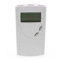
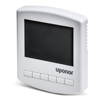
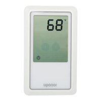
The Uponor heat-only thermostat
(A3030101) is designed for hydronic
heating applications.
The thermostat is power-sharing,
meaning it receives power for
operation by sharing voltage
with the connected wiring. This
eliminates any need for a third wire
or batteries, making the thermostat
simple to install, wire and service.
Note: The thermostat works
effortlessly with other Uponor
components. However, some
commonly used third-party devices
(e.g., relays, zone valves, etc.) may
have compatibility issues with the
thermostat. If connecting the
thermostat to a third-party control
device, refer to that device’s
installation instructions for specific
information regarding operation
with a power-sharing thermostat.
The Typical Wiring Schematics
section in this instruction sheet
features the most common wiring
applications. F
or additional help,
contact Technical Services.
Uponor U.S.: (800) 321-4739
Uponor Canada: (888) 994-7726
Tools Required
•
Small, flathead scr
ewdriver
•
Phillips scr
ewdriver (f
or
mounting hardware)
•
Wir
e stripper and cutt
er
Installation
Prior to installing the Uponor
thermostat, follow the instructions
below.
1. Thoroughly read this instruction
sheet to understand the proper
procedures for installation and
operation. Failure to do so
could result in damage to the
thermostat or its connected
equipment, and can also
create a safety hazard.
2. Ensure the function and rating
of the thermostat is suitable for
the application.
3. Only experienced and trained
professionals familiar with low-
voltage wiring should attempt
to install the thermostat.
4. Uponor recommends using
18AWG LVT wiring for all
low-voltage connections
(as r
egulat
ed by local
building codes).
Placing the Thermostat
Wher
e you plac
e the thermostat
is extremely important. Install the
thermostat appr
o
ximat
ely five f
eet
(1.75 met
ers) above the floor on
a smooth, flat surface. Avoid
mounting the thermostat in
the f
ollowing locations.
• Near or around windows
•
On outside walls
• Near fireplaces
•
In the corner of a room
• Behind doors
• On interior walls susceptible
to solar gains
• Near stoves, lamps,
televisions, etc.
• Damp areas
Technical Data
Operating 24VAC +/- 10%
Voltage
Maximum Load
1.3 Amps at 24VAC
4 x MVA
(part number A3020522)
6 x TVA (part number
A3010522, four-wire)
6 x TVA (Canadian model only,
part number A3020416,
two-wire)
Display Range 38°F to 99°F (2°C to 37°C)
Setting Range 38°F to 99°F (2°C to 37°C)
68°F (20°C) default setting
Minimum Limit 38°F (2°C) to maximum limit
50°F (10°C) default
minimum setting
Maximum Limit Minimum limit t
o 99°F (37°C)
86°F (30°C) default
maximum setting
Units User
-c
onfigur
able
Fahrenheit or Celsius
Memory Permanent settings and
mode without power
Freeze Protection Activation at 38°F (3.3°C)
De-activation at 39°F (3.8°C)
Resolution 1° displayed, 0.25° calculated
Temperature Shipping and storage —
Ranges
14°F to 158°F, (-10°C to 70°C)
Operation —
32°F to 104°F, (0°C to 40°C)
Humidity 20 to 90% non-condensing
Size 5" H x 2.72" W x 0.91" D