Home
Vaisala
Measuring Instruments
HMP3
Vaisala HMP3 User Manual
4
of 1
of 1 rating
96 pages
Give review
Manual
Specs
To Next Page
To Next Page
Loading...
M212022EN-D
User Guide
V
aisala Indigo compa
tible
humidity and t
emper
atur
e pr
obes
HMP3, HMP4, HMP5, HMP7
, HMP8, HMP9
, MMP8, TMP1
陕西威瑞仪器仪表有限公司
生产代理销售:实验检测设备
气象科学仪器设备
Tel:029-88186182
Web:www.xavery.cn
Email:sxvery@163.com
2
Table of Contents
Table of Contents
3
About this Document
9
Version Information
9
Related Manuals
9
Table Document Versions (English)
9
Table 2 Related Manuals
9
Documentation Conventions
10
Trademarks
10
Product Overview
11
Probe Structure
11
Basic Features and Options
11
Figure Probe Parts
11
Output Parameters
12
Table 3 Availability of Output Parameters
12
Additional Features with Indigo 200 Series Transmitters
13
Safety
13
ESD Protection
14
Regulatory Compliances
14
FCC Part 15 Compliance Statement
14
Canada ICES-003 Compliance Statement
15
Installation
16
Figure 2 Example Installation
16
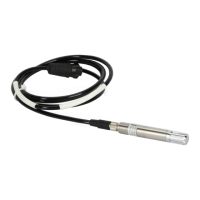
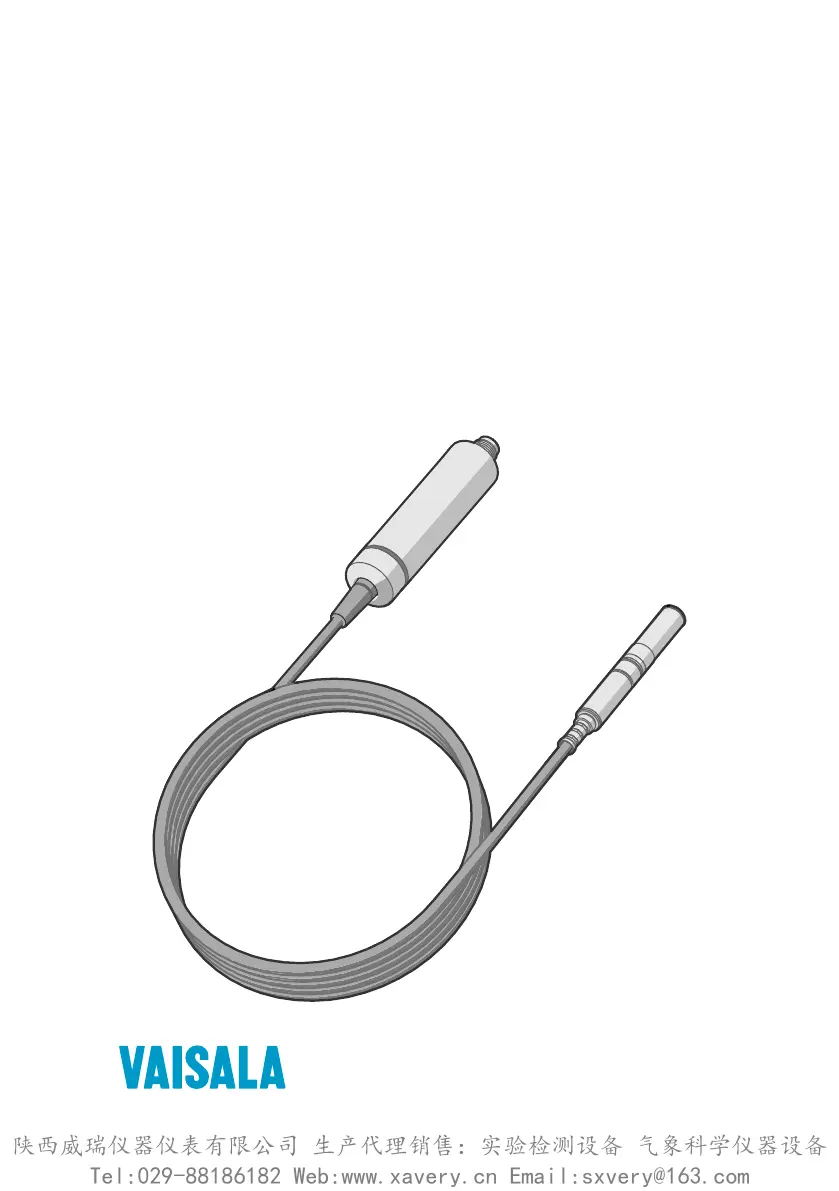
HMP3 Probe
17
Figure 3 HMP3 Probe Dimensions
17
HMP4 Probe
18
Figure 4 HMP4 Probe Dimensions
18
HMP5 Probe
19
Figure 5 HMP5 Probe Dimensions
19
Figure 6 Optional Mounting Flange 210696 Dimensions
19
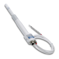
HMP7 Probe
20
Figure 7 HMP7 Probe Dimensions
20
HMP8 Probe
21
Figure 8 HMP8 Probe Dimensions
21
Attaching Ball Valve Kit to Process
22
HMP9 Probe
23
Figure 9 HMP9 Probe Dimensions
23
Installing HMP9 through a Cable Gland
24
Figure 10 Installing HMP9 Probe Head through a Cable Gland
24
MMP8 Probe
25
Figure 11 MMP8 Dimensions
25
TMP1 Probe
26
Figure 12 TMP1 Probe Dimensions
26
Wiring
27
Figure 13 M12 5-Pin A-Coded Male Connector Pinout
27
Figure 14 RS-485 Wiring
27
Configuration with Insight Software
29
Vaisala Insight Software
29
Installing Driver for the USB Service Cable
29
Connecting to Insight Software
30
Configuration Options
31
Figure 15 Connecting Probe to Insight
31
Figure 16 HMP5 in Insight Software
32
Using Probe with Indigo Transmitters
33
Indigo 200 Series Transmitter Overview
33
Figure 17 HMP7 Attached to Indigo 200 Series Transmitter
33
Figure 18 HMP7 Attached to Indigo 200 Series Transmitter with a Cable
34
Attaching Probe to Indigo 200 Series Transmitter
35
Figure 19 Attaching the Probe to Indigo 200 Series Transmitter
35
Wireless Configuration Interface Overview
36
Connecting to Wireless Configuration Interface
36
Figure 20 Enabling and Accessing Wireless Configuration Interface
36
Logging in to Wireless Configuration Interface
37
Figure 21 Indigo Login View
37
Maintenance
38
Cleaning the Probe
38
Chemical Tolerance
38
Table 4 Suitability of Cleaning Agents
38
Changing the Probe Filter
39
Replacing the Humicapâ R2 Sensor
39
Figure 22 HMP3 Probe Head with Filter Removed
40
Calibration and Adjustment
41
Adjustment Points and Requirements
42
Adjusting Measurement with Insight Software
43
Adjusting Measurement with Indigo 200 Transmitter
44
Figure 23 Calibration Page in the Indigo 200 Wireless Configuration Interface
46
Troubleshooting
48
Problem Situations
48
Error Messages
48
Table 5 Troubleshooting Table
48
Technical Data
51
HMP3 Specifications
51
Table 6 Measurement Performance
51
Figure 24 HMP3 Humidity Measurement Accuracy as a Function of Temperature
52
Figure 25 HMP3 Temperature Measurement Accuracy over Full Range
52
Table 7 Operating Environment
52
Table 8 Inputs and Outputs
53
Table 9 Mechanical Specifications
53
HMP4 Specifications
54
Figure 26 HMP3 Probe Dimensions
54
Table 10 Measurement Performance
54
Figure 27 HMP4 Humidity Measurement Accuracy as a Function of Temperature
55
Figure 28 HMP4 Temperature Measurement Accuracy over Full Range
55
Table 11 Operating Environment
56
Table 12 Inputs and Outputs
56
Table 13 Mechanical Specifications
56
HMP5 Specifications
57
Figure 29 HMP4 Probe Dimensions
57
Table 14 Measurement Performance
57
Figure 30 HMP5 Humidity Measurement Accuracy as a Function of Temperature
58
Figure 31 HMP5 Temperature Measurement Accuracy over Full Range
58
Table 15 Operating Environment
59
Table 16 Inputs and Outputs
59
Table 17 Mechanical Specifications
59
HMP7 Specifications
60
Figure 32 HMP5 Probe Dimensions
60
Table 18 Measurement Performance
60
Figure 33 HMP7 Humidity Measurement Accuracy as Function of Temperature
61
Figure 34 HMP7 Temperature Measurement Accuracy over Full Range
61
Table 19 Operating Environment
62
Table 20 Inputs and Outputs
62
Table 21 Mechanical Specifications
62
HMP8 Specifications
63
Figure 35 HMP7 Probe Dimensions
63
Table 22 Measurement Performance
63
Figure 36 HMP8 Humidity Measurement Accuracy as a Function of Temperature
64
Figure 37 HMP8 Temperature Measurement Accuracy over Full Range
64
Table 23 Operating Environment
65
Table 24 Inputs and Outputs
65
Table 25 Mechanical Specifications
65
HMP9 Specifications
66
Figure 38 HMP8 Probe Dimensions
66
Figure 39 Optional Ball Valve Installation Kit Dimensions
66
Table 26 Measurement Performance
66
Table 27 Operating Environment
67
Table 28 Inputs and Outputs
68
Table 29 Mechanical Specifications
68
MMP8 Specifications
69
Figure 40 HMP9 Probe Dimensions
69
Table 30 Measurement Performance
69
Figure 41 a W Measurement Accuracy
70
Table 31 Operating Environment
70
Table 32 Inputs and Outputs
70
Figure 42 MMP8 Dimensions
71
Table 33 Mechanical Specifications
71
TMP1 Specifications
72
Figure 43 TMP1 Temperature Measurement Accuracy over Full Range
72
Table 34 Measurement Performance
72
Table 35 Operating Environment
72
Figure 44 TMP1 Probe Dimensions
73
Table 36 Inputs and Outputs
73
Table 37 Mechanical Specifications
73
Accessories and Spare Parts
74
Figure 45 Optional Duct Kit 215003 Dimensions
74
Table 38 Connection Cables
74
Table 39 Accessories
75
Table 40 Spare Parts
75
Table 41 Spare Parts
75
Table 42 Accessories
75
Table 43 Spare Parts
76
Table 44 Accessories
76
Table 45 Spare Parts
76
Table 46 Accessories
76
Table 47 Spare Parts
77
Table 48 Accessories
77
Table 49 Accessories
77
Table 50 Spare Parts
77
Table 51 Accessories
77
Appendix A: Modbus Reference
79
Default Communication Settings
79
Function Codes
79
Data Encoding
79
Table 52 Default Modbus Serial Communication Settings
79
Table 53 Modbus Function Codes
79
32-Bit Floating Point or Integer Format
80
16-Bit Integer Format
80
Modbus Registers
80
Table 54 16-Bit Signed Integer Format Details
80
Measurement Data Registers
81
Table 55 Floating Point Measurement Data Registers (Read-Only)
81
Table 56 Integer Measurement Data Registers (Read-Only)
82
Configuration Registers
84
Table 57 Modbus Configuration Data Registers (Writable)
84
Device Identification Objects
87
Status Registers
87
Table 58 Device Identification Objects
87
Table 59 Modbus Status Data Registers (Read-Only)
87
Table 60 Error Codes in Register 0203
88
Test Value Registers
89
Table 61 Modbus Test Registers (Read-Only)
89
Modbus Communication Examples
90
Online Store
93
Warranty
93
Technical Support
93
Recycling
93
4
Based on 1 rating
Ask a question
Give review
Questions and Answers:
Need help?
Do you have a question about the Vaisala HMP3 and is the answer not in the manual?
Ask a question
Vaisala HMP3 Specifications
General
Brand
Vaisala
Model
HMP3
Category
Measuring Instruments
Language
English
Related product manuals
Vaisala HMP110REF
98 pages
Vaisala HMP60 series
98 pages
Vaisala HUMICAP HMP155
102 pages
Vaisala HUMICAP HMP45A
10 pages
Vaisala HM45
67 pages
Vaisala HPP272
66 pages
Vaisala CL31
142 pages
Vaisala CT25K
139 pages
Vaisala RT20A
59 pages
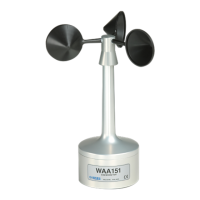
Vaisala WAA151
29 pages
Vaisala PR-23 Series
272 pages
Vaisala Radiosonde RS41-SGM
42 pages