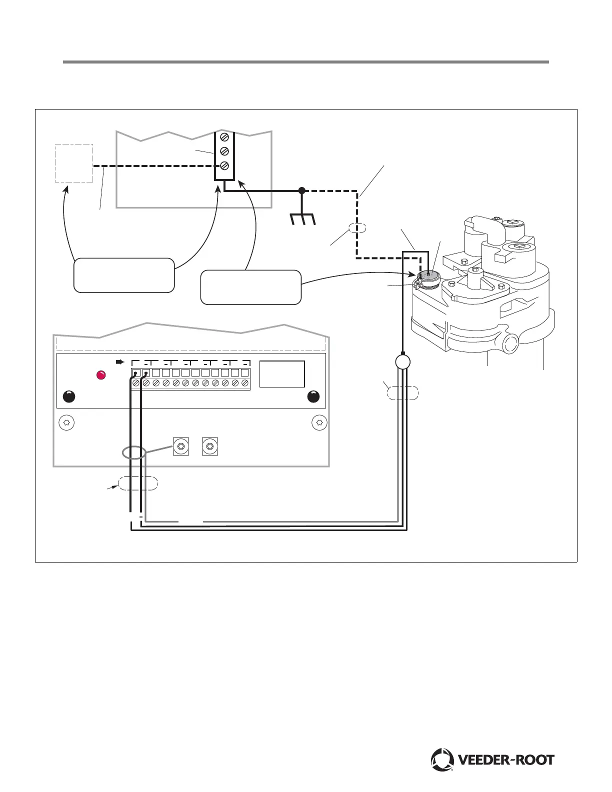
Figure 3.
NOTES:
1. All sensor wiring and intrinsically safe
connections installed in accordance with
576013-902 and appropriate site prep
manual (see related comments on page 1).
2. Intrinsically safe wiring shall be installed
in accordance with article 504-20 of the
NEC ANSI/NFPA 70 or local jurisdiction
having authority.
3. Do not connect wire that is attached to
the PLLD clamp to any intrins
ically safe
wiring.
012-1.eps
PLLD
sensor
Earth ground
bus
PLLD sensor
cable
PRESSURE XMIT
MAXIMUM SENSOR
OUTPUT RATINGS:
15 VDC
.15 AMP
+ + + + + +
1 2 3 4 5 6
PRESSURE LINE LEAK INTERFACE MODULE
Conduit or ducting
Attach cable shield
to ground lug closest
to conduit/duct entry
+
Intrinsically Safe Bay of Console
AC Mains Breaker Panel
Shield
Ground wire with 4 mm cross-
sectional area minimum. Connects
to the site’s earth ground.
2
PLLD sensor
grounding clamp
Tighten bolt until
clamp cannot be
rotated by hand
Non-Intrinsically
safe conduit
or ducting
Site Earth ground
Earth
ground
to TLS
Console
Intrinsically
safe conduit
or ducting
TLS ground wiring cross section
must be 4 mm
2
or larger. Connect
the barrier ground to the earth ground
bus at the power distribution panel.
Check continuity between
electrical panel earthing bus
and PLLD sensor body.
Check continuity between
TLS console ground and
electrical panel earthing bus.
 Loading...